Index
Dear MZ friends!
Please do not put aside these operating instructions because you presume to know everything that is said.
Nowadays it is true that most people have a good working knowledge of automative engineering, but
even the most experienced motorbike rider can still learn something.
For four decades, motorcycles have been built in Zschopau. For that reason the manufacturers make
every provision to supply you with a vehicle on whose reliability and working safety you may depend.
It is now up to you tomaintain these qualities. This does notmean that you should handle your 'ES'
like a crate of eggs, but if you follow our recommendations on running-in, proper fuel, maintenaince
and service, you will find that your 'ES' is practically instructible.
Therefore, always follow our recommendations. Your 'ES' will be thankful to you!
We wish you bon voyage!
VEB MOTORRADWERK ZSCHOPAU
TABLE OF CONTENTS
| 1. | Technical data |
| 1.1. | Engine |
| 1.2. | Carburettor |
| 1.3. | Electrical equipment |
| 1.4. | Gearing |
| 1.5. | Transmission of power |
| 1.6. | Chassis |
| 1.7. | Dimensions and weights |
| 1.8. | Filling quantities |
| 1.9. | Brake retardation |
| 2. | Fuel and lubrication |
| 2.1. | Fuel |
| 2.2. | Motor oil |
| 2.3. | Mixing ratio |
| 2.4. | Power transmission lubricants |
| 2.5. | Chassis lubricants |
| 2.6. | Shock absorber filling |
| 3. | The first start |
| 3.1. | Ready to ride? |
| 3.2. | We ride ... |
| 3.3. | ... up hill |
| 3.4. | ... down hill |
| 3.5. | Stopping and parking |
| 4. | Correct running-in |
| 5. | Riding with economy |
| 6. | Maintenance |
| 6.1. | Checking oil level in gearbox |
| 6.2. | Changing gear oil |
| 6.3. | Readjusting the clutch, replacing the Bowden cable |
| 6.4. | Cleaning and re-adjusting the carburettor |
| 6.5. | Air filter and intake muffler |
| 6.6. | Fuel shut-off cock and its filter |
| 6.7. | Checking the electic circuits |
| 6.8. | Dynamo and breaker |
| 6.9. | Regulator, ignition coil and fuse box |
| 6.10. | Filling and maintaining the battery |
| 6.11. | Replacing the bilux bulbs |
| 6.12. | Readjusting the asymmetric low beam |
| 6.13. | Very important: the condition of the spark plug |
| 6.14. | Chain lubrication, checking the chain slack; replacing the chain |
| 6.15. | Wheel alignment |
| 6.16. | Cleaning and re-adjusting the brakes |
| 6.17. | Teleskopic forks |
| 6.18. | Readjusting the stop light contact |
| 6.19. | The proper tyre pressure |
| 6.20. | Tyre mounting |
| 6.21. | Removing the residues of combustion |
| 7. | 'ES' 'cosmetic' |
| 8. | 'Mothballing' |
| 9. | Troubles - what to do? |
| 9.1. | First of all; condition of the spark plug! |
| 9.2. | Engine fails to start |
| 9.3. | Red control light fails to go out in spite of higher speed |
| 9.4. | Engine is running out of true |
| 9.5. | Engine fails to respond to throttle |
| 9.6. | Fuel consumption is too high |
| 9.7. | Battery fails to accumulate current |
| 9.8. | Bulbs do not burn |
| | Extra accessories |
| | Spare parts procurement |
| | After-sales service |
| | Lubrication chart |
| | Wiring diagram |
|
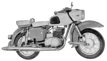
Fig. 1. ES 175/2 - ES 250/2
1. Technical data
1.1. Engine
nächster Punkt ; Index
| | ES 175/2 | ES 250/2 |
| Mode of operation | two-stroke reverse scav- | two-stroke reverse scav- |
| Type of cooling | enging air cooling
(relative wind) | enging air cooling
(relative wind) |
| Number of cylinders | 1 | 1 |
| Stroke/bore | 65/58 | 65/69 |
| Piston displacement | 172 cm³ | 246 cm³ |
| Compression ratio | 9:1 | 8,5:1 |
| Output at 5500...5600 r.p.m. | 13,5 DIN HP = 9,9 kW | 17,5 DIN HP = 12,9 kW |
| Maximum torque | 1.85 k.p.m. at 4800 r.p.m. | 2.5 k.p.m. at 4500...4700 r.p.m. |
| Lubrication | mixture method lubrication 33:1 ('Hyzet') oil | mixture method lubrication 33:1 ('Hyzet') oil |
Connecting rod bearing
(crankpin and piston pin) | needle bearing guided in cage | needle bearing guided in cage |
| Crankshaft main bearings | 2 bearings 6305 c 003 f | 2 bearings 6305 c 003 f |
| | 1 bearing 6302 | 1 bearing 6302 |
| Lubrication of Crankshaft bearings | by transmission lubricant | by transmission lubricant |
| Fuel | VK 'Normal' (OZ 79) | VK 'Normal' (OZ 79) |
1.2. Carburettor
nächster Punkt ; Index
| | ES 175/2 | ES 250/2 |
| | BVF 26 N 1-1
(starter carburettor) | BVF 28 N 1-1
(starter carburettor) |
| Carburettor data: | | |
| Passage in mm | 26 | 28 |
| Main jet | 100 | 107 |
| Needle jet | 65 | 67 |
| Slow running needle no. | 2 with 5 notches | 3 with 5 notches |
| Needle position from top | 3...4 *) | 3...4 *) |
| Starting jet | 90 | 100 |
| Idling jet | 40 | 40 |
| Slow running stop screw | 2...3 turns open | 2...3 turns open |
| Air filter | Dry air filter in intake muffler |
| *) Always observe the condition of the spark plug |
1.3. Elektrical equipment
nächster Punkt ; Index
| | ES 175/2 | ES 250/2 |
| Ignition | battery ignition with automatic spark advance | battery ignition with automatic spark advance |
| Ignition timing | 3.0 mm. before T.D.C. with balanceweights completely spread | 3.0 mm. before T.D.C. with balanceweights completely spread |
| Breaker point gap | 0.3 mm | 0.3 mm |
| Spark plug | 'Isolator' M 14/260 | 'Isolator' M 14/260 |
| Spark plug gap | 0.6 mm | 0.6 mm |
| Dynamo | direct current 6 V., 60 W. - s.t. 90 W | direct current 6 V., 60 W. - short-time 90 W. |
| Charging control light | (red) in speedometer | (red) in speedometer |
| Regulator | RSC 60/6 under left-hand side covering | RSC 60/6 under left-hand side covering |
| Battery | 6V., 12 a.h. (flat lead storage battery) |
| Ignition coil | 6V., under left-hand covering |
| Headlight | fixed, effective diameter 170 mm. |
| Dimmer switch | on handle bars, left |
| Tail light | effective diameter 95 mm. |
| combined with stop light | contact at rear break spanner |
| flashing indicator light | on both sides of handle bars (switch at right-hand side of handle bars) |
| Flasher | in headlight casing |
| Signal horn | under fuel tank |
| Light signal | is worked by means of push button under dimmer switch |
1.4. GEARING
nächster Punkt ; Index
| | ES 175/2 | ES 250/2 |
| Clutch | on the left tail shaft - in oil bath (5 friction disks with cork parts) |
| Gear shift | foot operated gear shift |
| Number of gears | 4 | 4 |
| Ratio of gears: | |
| 1st gear | 2.77:1 |
| 2nd gear | 1.63:1 |
| 3rd gear | 1.23:1 |
| 4th gear | 0.92:1 |
| Neutral gear indicating light | electric tell-tale lamp (green) in speedometer |
1.5. Power transmission
nächster Punkt ; Index
| | ES 175/2 | ES 250/2 |
| Ratio engine - gear box | 2.43:1 |
| by helical-toothed spur wheels | 28:68 teeth |
| Ratio gear box - rear wheel | 2.65:1 = 17:45 teeth | 2.14:1 = 21:45 teeth |
| by roller chain | 12.7 x 7.75 x 8.51 mm = 1/2" x 5/16" |
| | | (with side car: 2,65:1 = 17:45 teeth) |
1.6. Chassis
nächster Punkt ; Index
| | ES 175/2 | ES 250/2 |
| Frame | single-tube frame, welded. Flexible engine suspension in rubber blocks |
| Type of spring suspension | front and rear swinging forks |
| front | telescopic fork with hydraulic shock absorbing,
travel stroke 142 mm |
| rear | telescopic fork with hydraulic shock absorbing,
travel stroke 115 mm,
adjustable travel stroke |
| Wheels | wire wheels with uncranked spokes |
| Rim size: | |
| front | 1.85 B x 16 |
| rear | 2.15 B x 16 |
| Tyres | |
| front | 3.25 - 16 |
| rear | 3.50 - 16 |
| Tyre pressure (gauge pressure) | |
| front | 1.4 atm. gauge pressure | 1.4 atm. gauge pressure |
| rear | 1.9 atm. gauge pressure for solo riding | 1.9 atm. gauge pressure for solo riding |
| rear | 2.1 atm. gauge pressure with pillion rider | 2.1 atm. gauge pressure with side car for solo riding |
| | | 2.6 atm. gauge pressure |
| Brakes | full width hub brakes | full width hub brakes |
1.7. Dimensions and weights
nächster Punkt ; Index
| | ES 175/2 | ES 250/2 |
| Wheel base | 1325 mm. |
| Length | 2090 mm. |
| Width with mirror | 862 mm. |
| Height | 1060 mm. |
| Ground clearance, loaded | 170 mm. |
| Unladen weight | 155 kg. | 156 kg. |
| Carrying capacity | 165 kg. | 164 kg. |
| Total permissible load | 320 kg. | 320 kg. |
1.8. Filling quantities
nächster Punkt ; Index
| | ES 175/2 | ES 250/2 |
| Gear box | 750 cu.cm. motor oil Gl 60 (doped) in summer and winter |
| Fuel tank | approx. 16 litres fuel-oil mixture, ratio 33:1 |
| reserve quantity | approx. 1.5 litre |
| Telescopic forks | |
| front | 80 cu.cm. each |
| rear | 80 cu.cm. shock absorber oil 'Globo' each, viscosity 1.65...1.92 �E at 50�C = 8...11 cs. / 50�C |
| Top speed | approx. 100 km.p.h. | approx. 120 km.p.h. |
1.9. Brake retardation
nächster Punkt ; Index
With a favourable static friction value on gripping concete roadways
(superhighways) a brake retardation of 7.2 m/s² can be obtained providing the tyres
are in good condition and the brakes are properly adjusted.
Appropiate operation of both brakes yields the following braking distances:
| 30 km.p.h. | 4.8 m. |
| 60 km.p.h. | 19.4 m. |
| 90 km.p.h. | 44.0 m. |
These data are exclusive of reaction time of the rider.
Chassis serial number is at the rear of the right frame cantilever for fixing the
rear mudguard.
Engine serial number is stamped on the right side of the engine block.
In the interest of technical development we reserve the right of making modifications
to construction and equipment.
2. Fuel and lubricants
2.1. Fuel
nächster Punkt ; Index
Corresponding to the compression ratio, a motor gasoline with an octane
rating of 79, i.e. VK 'Normal', must be used for both ES types. For abroad, the gasoline
'Super' with an octane rating of 80 is recommended. The use of fuel with such a high octane
rating will cause too rich a mixture that can be compensated by lowering the slow running
needle.
|

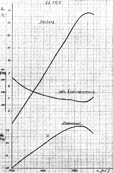
Fig. 2. Output, torque, specific fuel consumption
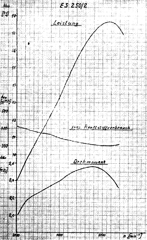
Fig. 2a. Output, torque, specific fuel consumption
Kraftstoff-Grundverbrauch ES 175/2
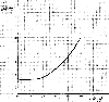
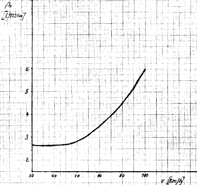
Fig. 3. Traffic fuel consumption
2.2. Motor oil
nächster Punkt ; Index
Connecting rod, cylinder and piston are supplied with oil by simple and
reliable mixture lubrication. Our exhaustive tests induce us to specify the exclusive
use of
Hyzet two-stroke motor oil
for the engine. This H.D. oil reduces mechanical wear and deposits
of combustion products.
Our MZ friends abroad are recommended to use exclusively special H.D. two stroke oils
(Shell 100, Shell 2T, Zwo-Ty-Mix, or the like). Warranty claims with respect to engine
failures caused by the use of straight motor oils will not be acknowledged by MZ!
If only straight motor oils, i.e. pure mineral oils are available (e.g. during extended
trips abroad), subsequent mixing
|
Kraftstoff-Grundverbrauch ES 250/2
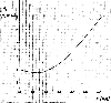
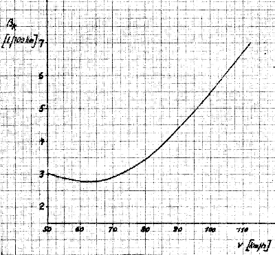
Fig. 3a. Traffic fuel consumption
|
with Hyzet is not permitted, since its additives (active matter) dissolve
the oil carbon in the combustion chamber. These emery type particles cause an early wear
of the piston, the working surface of the cylinder and the connecting-rod bearing.
Variation of motor oils is to be avoided.
2.3. Mixing ratio
nächster Punkt ; Index
In all cases the mixing ratio should be 33:1 also during the running-in
period. Ten litres of fuel must always be mixed with 0.33 litres of Hyzet oil. Too small
a quantity of oil will naturally cause damage to the engine and therefore it is
recommended that the filling of the tank be checked. If a mixing can is used, please
observe that no part of the relatively small quantity of oil remains in the can. This
part may mean a lot, especially in winter! If automatic mixing pumps are used, watch
that the pump is really changed to 33:1 and that the service station attendant does not
fill up with pure fuel by mistake. Too large quantity of oil won't do any good. As the
engine cannot consume the whole of the oil, part of it will settle in the silencer and
with the remainder you will befog the streets. It is clear that other road users will not
be pleased with these 'condensation trails'! Therefore do not listen to 'would-be experts'
and you will avoid oiled-up spark plugs and having to clean the silencer.
If the engine shows signs of overheating or if it trend to seize, a mixing ratio of 25:1
will not cure it, but the real cause must be traced and eliminated.
We have no objection to the use of additional oils, like 'upper cylinder lubricant' or
preparations with colloidal graphite, however, not until after the running-in period. The
latter is more suitable for a two-stroke engine. But only for the engine - on no account
the gearbox!
A mixing ratio of 25:1 is recommended to our MZ friends abroad who have no special
two-stroke oil at their disposal. This ratio means that 0.4 litre of mineral oil is mixed
with 10 litre of fuel = 4% of oil.
2.4. Power transmission lubricants
nächster Punkt ; Index
750 cu.cm. of motor oil GL60 are required for gearbox with primary drive.
On no account are graphited oils to be used as these will cause the clutch to slip. The
same trouble occurs when using Hyzet oil.
2.5. Chassis lubricants
nächster Punkt ; Index
All lubrication nipples of the chassis are to be lubricated with motor oil
by high pressure grease gun. Please observe following instructions.
If e.g. the link bracket pin is lubricated with grease against our instructions, sooner or
later the oilways will be clogged by resinified grease and consequently the links cannot
operate smoothly. Only the speedometer drive is lubricated with gear grease (Ambroleum).
Please consult the lubrication chart at the end of the operating
instruction.
2.6. Shock absorber filling
nächster Punkt ; Index
The front and rear shock absorbers are filled with 80 cu.cm. each of
'Globo' shock absorber oil. Viscosity 1.65 to 1.92 �E at 50 �C, i.e. 8 to 11 cs. at 50�C.
If this shock absorber oil is not available abroad, any other oil of the same viscosity
may be used. This is very important, for: in case of olwer viscosity the tension spring's,
'energy of return' in the telescopic fork will not be intercepted completely and the
machine will float. In case of higher viscosity, the tension spring returns too slowly
into home position. Consequently only half of the spring travel is available for the next
road shocks and the spring action becomes harder and harder!
3. The first start
3.1. Ready to ride?
nächster Punkt ; Index
The sales people have already prepared your motorcycle for riding; the
flashing trafficators are mounted, the battery is filled up and charged. No doubt a
common road trail was made to convince you of the perfect condition of your 'ES'.
Nevertheless, it is important to see for yourself, wheter your new machine is really
roadworthy and safe to operate.
Remove the checking screw and test the oillevel in the gearbox (Fig. 8);
check the lighting in all switch positions and observe especially the function of the stop
light and the flasher. The passage of the breather hle in the tank screwcap is to be
checked because it may be clogged by protective wax. This will cause the fuel feed to be
reduced and the piston may seize!
If the motorcycle is delivered to you by truck, the front or rear wheel is frequently
removed for reason of more convenient transportation. Therefore, you are advised to check
if both floating axles are securely tightened.
For protection, the entire machine was sprayed with a wax preparation. This hard wax
film is removed little by little by polishing with ordinary car polish until a high finish
is obtained.
The protective layer on the engine and exhaust pipe dissolves or evaporates by heating.
|
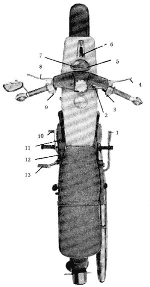
Fig. 4. Control levers and switches
- Brake pedal
- Choke lever
- Flashing light switch
- Hand brake lever
- Cut-out control light
- Combined ignition and lighting switch
- Charging control light
- Clutch lever
- Dimmer switch with horn button and flashing light indicator
- Foot change pedal
- Fuel shut-off cock
- Prop stand
- Kick starter
|
If you want your tyres to last then check the tyres pressure regulary and
not only before the first start! You may lock up the specified tyre pressure in chapter
'Technical data'. As th toe-cap of your shoes is not a reliable
measuring instrument, it is much better to buy yourself a tyre gauge, you may find that
the air pressure gauges at the service stations show varying pressures.
And now your 'ES' receives its specified fuel oil mixture, the recipe of which has already
been given in the preceeding pages.
If the vehicle licence and driver's licence are really in your pocket, you may start for
the first trip.
3.2. We ride ...
nächster Punkt ; Index
After your motorcycle has been standing idle for a prolonged time
(especially in winter) make it a routine practice to kick the starter several times
in nuetral position with the clutch disengaged.
This ensures that the unpleasant noise arising from sticking clutch plates during
engagement of the first gear will be avoided.
|
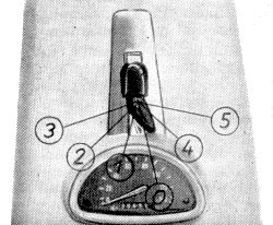
Fig. 5. Switch positions
| Position 0: | everything is switched off |
| | key can be removed |
| Position 1: | Ignition is switched on, |
| | no lights burning, daylight riding,
key cannot be removed. |
| Position 2: | Ignition is switched on, |
| | parking and tail lights are on (city night riding),
key cannot be removed. |
| Position 3: | Ignition is switched on, |
| | headlight and tail light are on, night riding,
key cannot be removed. |
| Position 4: | Ignition is switched off (parking position), |
| | parking and tail light are on
key can be removed. |
| Position 5: | Direct connection dynamo- contakt breaker. |
| | The machine can be changed into second gear, if battery is run down. |
In the parking popsitions 0 (daylight) and 4 (night) signal horn, stop
light and flasher are out of circuit.
Now, insert the ignition key into the ignition key into the ignition lock in position 0
and turn it into position 1, thus the ignition is switched on and in confirmation the
red charging control light in the speedometer lights up.
|
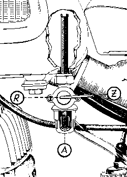
Fig. 6. Fuel shut-off cock
Z = closed, A = open, R = reverse
(To show both gauze filters, cross-section of the fuel tank and filter cap is given)
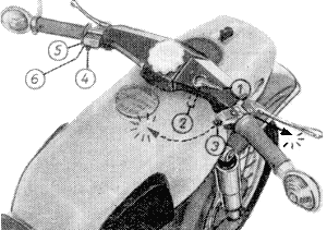
Fig. 7. Choke lever
- Zu = Riding position
- Cold starting position
- Flashing light indicator switch
- Dimmer switch
- Push button for horn
- Push button for the flashing light indicator beneath the switch
|
The green neutral gear indicating light, in speedometer at the right, must
light up as well. If not, shift the foot control pedal through the gears, the neutral
position is arranged between 1st and 2nd gear (Fig. 8).
Now place the fuel shut-off cock into position 'Auf' (on). For cold starting the
engine needs a richer fuel air mixture; therefore, pull out the choke lever (towards the
rider), (Fig. 7).
Close the throttle twist grip completely, otherwise the starting gear remains
ineffective!
Then the kick starter is vigorously operated until the engine runs. As soon as the engine
has started up th choke lever is closed, i.e. it is pushed forward into position 1.
With low outside temperatures (in winter) the choke lever is only half closed and during
the ride, when the engine is taking the gas willingly, it is closed completely.
It is not necessary to warmup the engine; therefore, depress clutch lever to limit stop
and shift into first gear by pushing down the foot control pedal (to limit stop). Release
the clutch lever slowly while slowly (never with a jerk) opening the throttle
twist-grip. Both operations must be synchronised in exactly the same way as your riding
instructor taught you. Do not move off with a jerk, so that your 'ES' jumps forward, nor
stall the engine.
On reaching a speed of approx. 25 km.p.h. depress the clutch lever and simultaneously close
the twist grip. Shift the foot
|
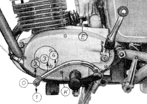
Fig. 8. Foot change pedal
The arrows show the direction of gear shifting for the separate gears. The neutral
gear-lever position (0) is half way between the first and second gear.
(K) Control plug for checking the oil level in gearbox
(E) Filling connection for gearbox lubricants
|
control pedal to second gear and swiftly release the clutch, at the same
time opening the throttle smoothly.
On reaching a speed of 45 km.p.h. shift to third gear and at 70 km.p.h. to fourth gear in
the same way. Please not that these speeds hold good for a running-in period of approx.
1500 to 2000 km. Please observe chapter ''Correct running'!
3.3. ... up hill
nächster Punkt ; Index
Whenever the engine cannot take an incline in fourth gear, i.e. if the
speed drops under 70 km.p.h., it is necessary to shift to the lower third gear at the
right time:
de-clutch, close twist grip only half (double de-clutching),
push down foot contol pedal,
angage the clutch and open throttle again.
This is telegraphic style indeed, but in practice these operations should
be performed still more rapidly to prevent the motorcycle falling back. Otherwise it may
be necessary to shift to the next lower gear. If the speed decreases still further, shift
down to second gear at approx. 45 km.p.h. and to first gear at 25 km.p.h. Use the clutch
exclusively for engaging and disengaging; frequent 'slipping' will wear out even the best
clutch lining in the long run!
3.4. ... down hill
nächster Punkt ; Index
Perhaps you think that there is nothing to riding down hill. In actual
fact there are a few points which must be watched. It is natural that the operating
temperature of the engine will rise after you have taken a long steep hill smoothly and
in full swing. If you close the throttle twist-grip abruptly and completely when riding
down hill, the engine will receive hardly and fuel-oil mixture (only via the slow running
bore) and consequently the lubrication will be very poor.
Therefore, close the throttle twist-grip slowly to avoid seizing of the piston. It is good
practice to pull the choke lever out for a short period of time during the first
running-in kilometers. The 'internal cooling' will rapidly reestablish the normal
operating temperature.
As far as the roadway and the traffic permit, open up the throttle a little now and then
and especially during a long downhill ride.
3.5. Stopping and parking
nächster Punkt ; Index
Apply the brake while slowly closing the throttle twist-grip; de-clutch
and shift down to neutral. Do not stall the engine! If you have the intention of parking,
switch off the ignition and close fuel shut-off cock. Do not forget to withdraw the
ignition key.
|
Fig. 9. Theft prevention
|
Do not keep the spare key on the key ring, but put it in an easily
accessible but visible place on the machine. If need be, secure the spare key with
adhesive tape.
If you use your machine mainly on week-ends, it is good practice to run the warmed-up
engine 2 to 3 seconds with the throttle twist grip 1/4 open, prior to parking. Withdraw
the ignition key and close the throttle twist completely after the engine has come to a
standstill. Thus all engine parts which are susceptible to corrosion (see:
'Correct running-in' Section 1), will be protected against corrosion for
a short period of time, i.e. from one week-end to the next.
4. Correct running-in
nächster Punkt ; Index
In spite of super finishing, like lapping and honing, the running and
bearing surfaces have still a certain degree of roughness and they will rub one another
smooth only in the correct course of operation. This process should not be forced for
the new parts sliding against each other must be given sufficient time to adjust. This
applies in particular to the piston and cylinder; their large sliding surfaces must be
covered with a uniform and uninterrupted oil film. If there is still a small pressure
mark and the piston is not allowed the time to adjust itself to the cylinder, it will
'seize'. The metal-separating oil film will be interrupted be prolonged riding with
throttle wide open because
high speeds (r.p.m.) = higher surface and bearing pressure.
Just as bad as the expression 'seize', is the damage which you can cause.
If the engine has seized without de-clutching in time, cylinder and piston are to be
removed and the latter repolished with a smooth-cut file or an oilstone. (never use emery
cloth!).
An experienced rider always on the clutch lever for immediate clutch disengagement. Thus,
serios damages can be avoided. Of course, even a slight seizure of the piston leaves
visible traces, but these pressure marks will be worked off after a period of careful
riding!
Under no condition is correct running-in related only to covering a certain distance or
to a pre-determined running-in period, but mainly to the way in which the new machine is
handled. The engine of very expensive motor cars are normally run-in on the test bench,
but this is not possible for motorcycles because of the price factor.
Running-in is a period that cannot be side-stepped by you and we therefore request you
to observe the following running-in procedure so that you will own an efficient,
roadworthy machine after covering a distance of 1550 to 2000 km.
- Never let the engine run unnecessarily in neutral position, but ride off immediately
with permissible loed in order to allow the engine to reach its operating temperature
as soon as possible. This is required because fuel combustion separates carbon dioxide
and water in every engine. If leaded fuel is used, hydroclorid acid from the
tetraethyl lead is added. These 'Evil Spirits' are diposited inside the cold engine
and cause varying amounts of corrosion (rust formation) this is the main cause of
premature wear!
- On purpose, we have abstained from limiting (throttling) the throttle valve travel
during running-in period. We leave it to your good sense not to exceed the following
speeds during the first 500 kilometers:
| | ES 175/2 | ES 250/2 |
| 1st gear | 25 km.p.h. | 25 km.p.h. |
| 2nd gear | 45 km.p.h. | 45 km.p.h. |
| 3rd gear | 65 km.p.h. | 70 km.p.h. |
| 4th gear | 80 km.p.h. | 85 km.p.h. |
Only after 500 km. have been covered can the machine be given full throttle for brief
periods (with gradual extensions until termination of running-in period). The more
kilometers your engine has covered, the higher and longer you may stress it.
- Change gears at the right time so that the engineneither overspeeds in too low a gear
nor jerks in too high a gear. If you are climbing a hill which the engine can just
make in fourth gear and with throttle wide open, it is better to change down to third
gear and only half open the throttle. The medium speed range is best suited for your
engine and consumes little fuel. In this connection please observe the ratio of
output, torque and specific fuel consumption in Figure 2 'Traffic
fuel consumption'.
- Be careful an superhighways not to lose your sense of speed or ride with throttle
twist-grip permanently in the same position. On country roads you are compelled to
ride in different speeds due to bends, passing through towns etc., and this is the
safest and most reliable running-in method!
- Clean carburettor and filter of the fuel shut-off cock frequently to avoid any
reduction of the fuel supply. Too lean a fuel-air mixture will result in an overheated
engine and possibly in a siezed piston!
- The fuel oil mixing ratio of 33:1 has to be maintained during the entire running-in
period; a special running-in jet is not required. Only the slow running (jet) needle
is adjusted on notch higher for both ES types (see 'technical data').
The condition of the spark plug is always decisive for readjusting the carburettor
adjustment. (see chapter 9.1.). The carburettor adjusting valves
indicated under 'technical data' are only to be considered as basic
adjustments.
- It is not recommended to add colloidal graphite or molybdenum disuphide (MoS2)
to the fuel oil mixture for the running-in period because this way the running-in
process cannot be controlled and will be delayed.
Finally, we must stress the need for extremely careful treatment and
precaution: if the speeds in the various gears are not increased systematically, the
engine will not be run in after 5000 kilometers. Of course, you may take along your
pillion rider during the running-in period; due to the higher load,however, it is necessary
to change down to a lower gear sooner.
5. Riding with economy
nächster Punkt ; Index
An experienced rider will always ride with economy. By a smooth riding
technique in conformity with the traffic situation; without extremely high speed and the
involved 'emergancy brakings'; he spares the tyres, chain and fuel! Fast riding wastes
fuel and therefore money. Not only with the 'MZ', but with other motorcycles as well.
You also pay the railways an excess fare for fast trains!
Learn to apply the brakes correctly because 'safety first' should be the main rule!
On wet or slippery or ice-bound roads, always use both brakes with appropriate care. Only
through permanent use will the front-wheel brake remain fully effective. When braking, the
weight of the machine is transferred to the front-wheel and therefore achieves a better
braking effect. By applying both the brakes simultaneously and with the proper touch, you
can employ the full braking effect on wet roads too. On the other hand if it should happen
that a five-ton truck should stand across our path and the front wheel brake is inoperative
or it jams, because it has never been used, then ... yes, what happens then is left to your
own imagination.
Avoid braking in bends since this is always associated with danger of side slips and
skidding. Throttle down before the bend, apply the brakes and open the throttle at the
centre of the bend!
Practice - at first with due care - on traffic free side roads until the simultaneous
operation of both brakes has become a reflex action. Then you will automatically
respond with the proper 'braking proportion' in dangerous situations, for the wheels must
not lock because then the traction of the tyres will be reduced. Moreover, you and your
motorcycle will go into a skid which may likely end in a crash.
The man must be master of the machine and not vice versa and therefore we should
like to add some advice from our own experience for your personal well-being, that is, as
fas as motorcycling is concerned:
Wear suitable clothing, because it is not possible to operate the brake or clutch with the
proper touch, if fingers and feet are stiff with cold. The physical discomfort lengthens
the time of response (reaction time) in case of dangerous traffic situations! When making
long trips in midsummer do not ride in shorts and with the collar of your shirt wide open.
If some vicious insect, unintentionally landing on the naked part of the body, responds
with a bite, this will not only be painful but also distract your attention from the road
traffic for a moment. Sandals and similar footwear without heels may be rather comfortable
in midsummer but they are not suited to motorcycling. The heels should give your feet a
proper grip on the foot rests; without heels your feet could slip from the foot rests and
brake pedal in case of emergency braking, just when fractions of a second count.
Well fitting, draught free goggles are just as important as a correctly fitting safety
helmet. The tiniest insect in the eye of the rider will blind him and the 'ES' would be
without operator temporarily.
Take the trouble of calculating the impact with which a beetle weighing 1 gramm will hit
you when you are travelling at 80 km.p.h.
|
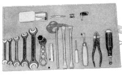
Fig. 10. Service tool kit
(Air pump under the left side panelling)
6. Maintenance
nächster Punkt ; Index
The tool kit enables you to perform all maintenance jobs yourself. Perform
these jobs concientiously at the specified intervals, otherwise you will be compelled to
carry them out on country roads or superhighways at the most inconvenient times. In order
that nothing may be forgotten, the use of the lumbrication and
maintenance chart at the end of these operation instructions is
recommended.
6.1. Checking oil level in gearbox
nächster Punkt ; Index
Theoillevel in the gearbox is to be checked before starting on any long
trip, but atthe latest after every 1000 km. After
|
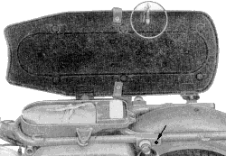
Fig. 11. Double seat, opend
(service tools, safety lock)
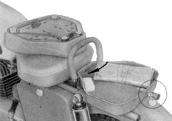
Fig. 12. Single seats pillion seat removed
(service tools, safety lock)
|
unscrewing the control plug (see Fig. 8) oil should flow
out ot the plug hole. You may tip the motorcycle slightly sideways to check how much
lubricant is missing.
If required, fill up with oil until it flows out of the plug hole. The filler hole is
located underneath the carburetter cover.
6.2. Changing the gear oil
nächster Punkt ; Index
Ther gearbox lubricant is to receive its first change after approx. 500 km.
and from then on after every 10000 km. The engine should be warmed up so thet any abrasive
matter and oil sludge will flow out as well. To drain, remove the two external drain plugs
located on the left of the clutch
|
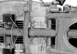
Fig. 13. Bottom of motor block
- Drain plug on clutch case cover (primary drive)
- Drain plug for gearbox
- Shift stop
- Rubber blocks of the flexible engine mountings, front
|
cover (1) and on the right side of the gear box (2). The latter plug is
magnetic for retaining abraded metal particles. The two central screws which are located
close together (3) serve as the gear shift stop and must not be screwed out.
After draining the used oil completely, screw both drain plugs in again, fill with 0.5
litre of flushing oil and close the filler hole. After you have ridden the machine around
the block a couple of times, drain the flushing oil completely and fill with 750 cu.cm. of
pure motor oil GL 60. On no account use graphited oil or oil with MoS2 additive
(molybdenum disulphide) nor Hyzet oil; these oils will cause the clutch to slip without
fail.
On no account fill with more then 0.75 litre. It will not make your 'ES' faster but slower
- the clutch will operate like a 'dynamometer'because it is completely standing in oil.
Futhermore, the superfluous oil will be forced out through the vent hole of the filler plug
and 'lubricate' the rear wheel tyre and the socks of your pillion rider!
6.3. Readjusting the clutch, replacing the Bowden cable
nächster Punkt ; Index
The free play of the clutch lever on the cable should be approx. 3 mm. If
it is less, the clutch will slip; if it is more, the clutch cannot be properly disengaged.
Changing gears will be a noisy operation. Adjustment is performed on the clutch lever by
means of the rapid-adjuster. Use the clutch only for those operations it is meant for -
namely for gear shifting!
|
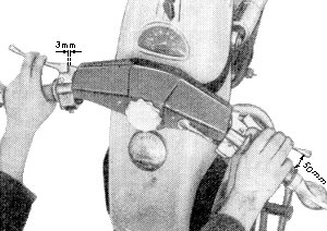
Fig. 14. Clearance on clutch and hand brake lever
|
When stopping before barrier level crossings or traffic lights shift to
neutral position. Do not conquer the last meters of a step hill with slipping clutch -
gear shifting is easy!
|
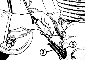
Fig. 15. Replacing the clutch cable
(showing cross-section of tube for better view)
|
To replace the Bowden cable, remove the inset (1) after withdrawal
of the cable cover. After unscrewing the cover (2) the nipple (3) can be pressed out of
the clutch operating linkage and the Bowden cable can be replaced. Reassembly is performed
in the reversed sequence of operation.
6.4. Cleaning and re-adjusting the carburettor
nächster Punkt ; Index
In the carburettor an air fuel mixture is atomized in the carburettor.
Provided both components are mixed in due proportion - 15 parts of air and 1 part of fuel
- the carburettor is well adjusted and the engine will give the specified performance.
Too much fuel results in delayed combustion similar to operting with late ignition.
This means poor performance, a considerable formation or deposits and higher fuel
consumption.
Too little fuel - when accelerating - causes the extraneous noise knowan as 'fuel
pinking'; spontaneous ignition occurs well before T.D.C. There is nothing left for the
spark plug to ignite since the engine continues running even with ignition switched off.
With throttle wide open, misfiring ar carburettor blow-back will arise without
substantially increasing the speed of the engine. The resulting overheating causes
seizing of the piston.
|
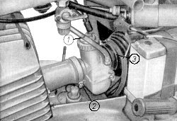
Fig. 16. Dismantling the carburettor
- Sliding housing cap with nut
- Clamping screw on suction connection
- Clamping ring on induction pipe
|
Now we hope that you are convinced of the importance of the correct
carburettor adjustment and of the periodic clearing of the carburettor. In the next pages
we describe how this is done.
After unscrewing the slotted nut, the carburettor cover can be removed and the fuel hose
can be pulled of the nipple. Then both side-panellings are removed after unscrewing the
knurled nuts. Unscrew the lock nut (1) and withdraw the entire slide valve casing cover
together with gas slide valve. Loosen nut of clamp screw (2) at the suction connection
and wire clamp ring (3) at induction pipe; now the carburettor can be removed from the
suction connection by lateral twisting.
Any impurities entering the carburettor will deposit first in the float chamber; therefore
first of all clean the float chamber thoroughly with petrol. Next unscrew the idling jet,
starter jet, main jet and slow running stop screw. Blow through the idling bore (ending in
the mixing chamber) arranged in the seat of the pilot jet, with compressed air (your air
pump will do). Never use a needle or a piece of wire not be jets any longer - use a
bristle from mother's broom.
If need be, unscrew the jet holder, it is possible that the pintle nozzle has come loose.
Check the sealing washer of the 'tickling piston', if in spite of proper carburettor
adjustment engine gets too rich a mixture in the lower speed range. Either the washer does
not seal because it is damaged or the Bowden cable setscrew is screwed out too far, so
that the sealing washer cannot bed down with closed choke lever.
|
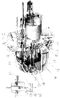
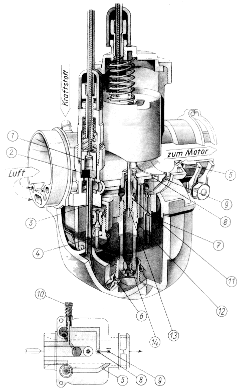
Fig. 17. Carburettor 26 N 1-1 and 28.5 N 1-1
The schematic drawing shows the course of the passages in the carburettor.
- Tickling piston
- Gasket
- Choke tube
- Float valve
- Starting duct
- Starter jet
- Pilot jet
- Reducing bore
- No load bore
- Slow running stop screw
- Pintle nozzle
- Nozzle holder
- Slow running needle
- Main jet
Luft - AIR
Kraftstoff - FUEL
zum Motor - TO ENGINE
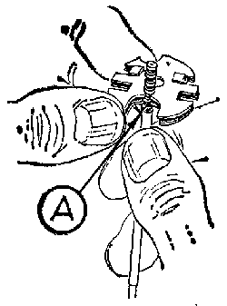
Fig. 17a. When adjusting the slow-running needle observe that the notch counts which
engages into the lower step of the needle holder. Position (A) shown in Figure 17a
corresponds to needle position 5.
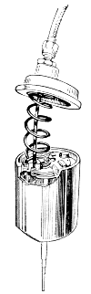
Fig. 17b. The needle holder with slow-running needle should lie flat on the bottom of
the gas slide valve; it is held by the pressure spring.
|
A clearance of 2 mm. between Bowden cable cover and setscrew is required
in order that the tension spring will close the tickler completely and thus shut off the
passage of the fuel air mixture. When cleaning the carburetter handle the centre float
with utmost care.
If both floating bodies are crushed against themselves or if the link for lifting the float
needle is deformed, the fuel level can no longer function properly. Consequently the engine
cannot run satisfactorily any more or it cannot run at all.
Re-assembly is to be performed in the reverse sequence of operation. We assume that
you placed the cleaned carburettor components on a clean cloth. Nevertheless, wipe off all
sealing surfaces and gaskets once more.
Clean the rubber connection of the air filter assembly before mounting the carburettor.
All adjustment data are indicated in the 'Technical data'. These data
are always to beadhered to, i.e. during and after the running-in period, for summer and
winter operation. The setting of the main jet also remains unchanged. Only the slow
running jet needle is reset so that the condition of the spark plug remains perfect; see
chapter 6.13. By raising the needle, the engine gets more fuel - by
lowering the needle it gets less fuel.
If the setting range of the slow running jet needle should not be sufficient, never use
larger or smaller main or idling jets to compensate, but locate the actual cause and
eliminate it.
In case of a too fine adjustment over the entire speed range, the engine will probable
get 'secondary air' (suction connection, suction pipe, filter case). See chapter
6.5.
The inverse proportion occurs when after a long period of operation the needle seat in
the float valve is considerably worn. In this case a smaller main jet will not help (the
engine will 'drown' in spite of this, if you do not close the fuel shut-off cock
immediately). Only a new float valve will help.
The proportional distribution of operations in the carburettor is as follows:
Main adjustable range of idling jet from 0 to 1/8 throttle valve travel (effective up
to throttle wide open).
Adjustable range of needle from 1/4 to 3/4 throttle valve travel.
Adjustable range of slide valve aperture up to 1/4 throttle valve travel.
Main adjustable range of main jet from 3/4 to throttle wide open (affects the entire
range however).
There is hardly anything more embarrassing than to be lined up with other
vehicles in front of traffic lights and the engine stalls when the lights are switched to
'green'.
In order to avoid anything similar happening to you, here is a detailed description of
idling adjustment.
Run your 'ES' until it is thoroughly warmed up (do not take this too literally, though
it means approx. 110�C) and
|
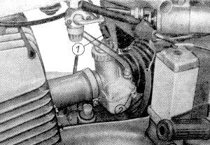
Fig. 18. Idling adjustment
- Setscrew for Bowden cable of gas slide valve
- Slow running stop screw
|
put it in a perfectly level position on blocks. Of course, the carburettor
should also be level, otherwise the fuel level will not be correct in spite of the centre
float.
Close idling mixture screw (1) completely and open again by 2 1/2 turns. Screw out the
Bowden cable setscrew (1) until the engine just continues running with closed throttle
twist-grip.
As a test, slowly turn the idling mixture screw in and out until you find the maximum
speed position.
Screw the Bowden cable setscrew in until the idling speed is normal again. Now screw in
the mixture screw by 1/4 turn (for reasons of better transition with a cold engine). The
term idling speed is to be understood as follows: a small tension spring is fixed in the
throttle twist-grip between the slide valve and the Bowden cable abutment. This spring
allows two postion:
- in released state the spring is the stop for 'idling speed'. Regulating is done with
the setscrews of the Bowden cable.
- If the throttle twist-grip is still further closed against the spring pressure, the
throttle valve will completely close the carburettor transfer port. (provided that
the slide valve casing is not worn owing to a long operating period).
With this flexible stop and the two resulting positions of the throttle
twist-grip the sports rider need not abstain from carrying out the idling adjustment.
Down hill the throttle twist-grip is completely closed. Thus the components of the power
unit are not loaded by sporadic irregular power strokes. Chain and gear wheels will have
a longer live!
To stop the engine, close the throttle twist-grip completely and switch off the ignition.
If throttle valve closes the passage completely, the engine will no longer receive an
ignitable mixture and consequently pre-ignition cannot occur.
A small brake screw (slotted screw) on the collar of the throttle twist-grip prevents the
automatic return of the throttle twist-grip. (to be adjusted)
To a certain extent the idling system is a self-contained miniature carburettor supplying
additional mixture over the entire speed range. Therefore, an over-rich idling adjustment
may be the cause for excessive fuel consumption.
On the other hand - if the idling mixture screw is screwed out too far - the fuel air
mixture ratio in the idling range is too lean. Besides a bad transition when accelerating
with a cold engine, it may be possible that the engine tends to seize after a long trip
with the throttle wide open and after abrupt closing of the throttle twist-grip.
Two things are important in connection with idle running adjustment:
- Idling speed. This speed should be so low that the engine is running, otherwise the
gears will grate.
- The proper fuel air mixing ratio otherwise ... see above!
6.5. Air filter and intake muffler
nächster Punkt ; Index
For combustion the engine requires considerable quantities of air.
Unfortunately this air is not dustfree and therefore it must be cleaned in the air-filter
unit. According to the condition of the roads, the dry air filter is to be cleaned after
every 1,000 to 2,000 km.
The paper filter element may neither be washed out nor oiled, but only carefully dusted.
The paper filter element is to be removed and renewed every 10,000 km.
|
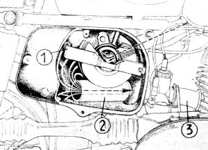
Bild 19. Intake muffler with air filter.
Cross section of filter element
- Holder
- Induction pipe
- Intake connection
|
For removing or exchanging the filter element the tension spring is to be
unhinged from the holder (1). When installing the filter element see that the holder is
located perfectly flat and air tight otherwise it might provide secondary air. The casing
and the cover have to be perfectly airtight, therefore beware of damaging the gaskets. Do
not change the spring suspension of the pressed material casing from its position; the air
filter will become ineffective through cracks. The suction pipe (2) on the casing passage
must be airtight.
The induction ait is sucked through the upper frame tubing from the almost dustfree zone
to the control head.
A wet filter element is impermeable to air and therefore unserviceable. Fuel consumption
would increase considerably.
6.6. Fuel shut-off cock and its filter
nächster Punkt ; Index
Guaranteed pure benzine can be purchased at the chemist's only. Therefore
the fuel shut-off cock of your 'ES' is equipped with two filters. One gauze filter before
the inlet (see Fig. 6) and a second one before the outlet in the filter
cap. The lower filter is easily cleaned: unscrew cap, unscrew filter, wash out in petrol
and re-assemble.
Cleaning the intake filter is not quite as easy, the fuel is to be drained off and the
shut-off cock is to be removed. Attention! The upper part of the cap nut has a right-hand
thread and its lower part has a left-hand thread. Pull off the filter, wash it out in
petrol: turn the cock into 'reverse' position and blow through it vigorously from its
outlet and wash out once more if required.
Check rubber gasket (remove levr); the passages might be narrowed owing to over-tightening
of both screws. In this case too little fuel is supplied. If re-adjustment of the
carburettor is required, first of all pull of the fuel hose and check the fuel supply
by opening the fuel shut-off cock for a very short period of time. If only a very weak
stream of fuel flows, the shut-off cock must be cleaned, otherwise the piston could seize
even in an engine which has been well run-in over a long period.
6.7. Checking the electric circuits
nächster Punkt ; Index
While giving the machine its routine clean, check all electric circuits
for possible chafed spots. Damaged insulation is to be bound with insulating tape; a roll
of insulating tape packed in a plastic bag is placed in the front of the headlamp shell.
Check all flat plug-type connections for oxidation and tightness.
6.8. Dynamo and breaker
nächster Punkt ; Index
The dynamo does not required much servicing,only the grease felt of the
breaker is to be provided with 2 to 3 drops of Hypoid or B-2 oil every 2,000 to 3,000 km.
(hypoid oil is a viscous gear oil of SAE 90). Only the highest point of the cammay lightly
touch the grease felt otherwise the lubricant will be slung out. If the grease felt lies
close to the full circumference of the cam, the balance weights of the advance mechanism
cannot twist the cam to advanced ignition! With late-ignition the engine cannot
arrive at its nominal speed and will become abnormally hot!
Check the contact breaker points for erosion every 3,000 km. Minor pits are to be
eliminated with a contact file. How-
|
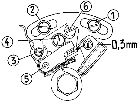
Fig. 20. Checking and readjusting the breaker point gap
|
even, it is better practiceto disassemble the anvil and the contact arm and
refinish them with an emery file. Do not us emery paper or emery cloth!
When deep pitting has occured, both parts are to be renewed. Heavy arcing indicates that
the contact points are not closing (readjust contact angle) or that the condenser is
defective. It is possible that the latter has a bad body contact. Heavy arcing causes
abnormal erosion and weakens the ignition sparks!
To replace the contact breaker do not loosen the slotted screw (1) and (2) since this
would change the ignition timing.
First unscrew locking screw (3) (current supply from condenser) and then slotted screw
(4), remove contact breaker and pull contact arm of bearing pin (5).
When reassembling provide the bearing pin with one drop of oil; the contact arm must be
able to rotate very easily. The eccentric screw (6) servest for the easy setting of the
contact breaker points' gep. The specified gap for both ES types is 0.3 mm. in the highest
cam position. While measuring, the feeler gauge (in service tool kit) must not jam, nor
clatter, but must slide between the contacts with just perceptible resistance. The contact
breaker points' gap is directly connected with ignition timing.
The cam bearer i.e. the cylindrical stud on which the contact breaker cam is mounted, is
to be lightly greased approx. every 5,000 km. Clean the bearing positions with petrol and
apply a thin layer of high ,elting-point grease (Ceritol M 28 T 5) in advance.
When reassembling note the position of the marks: the '0' on the cam must point to the
'0' on the cam bearer.
If the cam bearer is badly worn through lack of grease, the contact breaker lifts the
contacts irregularly (possibly even two times per crankshaft revolution). This causes
the engine to stall; often the actual cause cannot be found.
Accurate ignition timing together with proper operation of the carburettor is the
prerequisite for easy starting and good performance in all speed ranges. Therefore, this
job should be left to an authorized motor workshop since it has the necessary setting
gauge (with dial gauge) and test lamp available.
Every 10,000 km. the dynamo and governor are to be checked by an automatic-electric service
station for: wear of carbon brushes; cleaning of commutator; readjusting the
voltage-current regulator etc.
6.9. Regulator, ignition coil and fuse box
nächster Punkt ; Index
The regulator and the ignition coil require hardly any attention; only the
tight fit of cable plugs needs to be checked every 5,000 km.
The connecting terminals of the fuse box as well as the contact points of both 15 A fuses
may be subject to oxidation after a long period of operation. Remove the oxide, polish and
apply a thin film of acidles mineral jelly to these spots (polish cable ends too). Many
motorcyclists are still unaware of the fact that these (and other) poor contact points
will result in line losses of 50% and more.
The air pump as well as two holders for rubber rings receiving a spare inner tube are
placed inside the left side panelling.
6.10. Changing and maintaining the battery
nächster Punkt ; Index
If the changing control light burns only faintly and the horn only gives
a raucous croak after inserting the ignition key in the ignition lock, the battery is
run-down. Run-down in
|
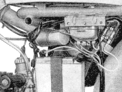
Fig. 21. Left side panelling removed
|
a twofold way - no current - no acid - the plates are dry (partly at
least). Certainly, the machine can be set going in second gear with the ignition lock
in position 5, but for the future a regular battery service will be much better
than optimism!
The new lead battery is treated as follows:
Fill the cells with battery sulphuric acid (specific gravity 1.24 - in the tropics 1.22)
up to the upper marking. This means: up to the lower side of the plastic strainer,
not above it!
Charge with 0.6 A after 2 to 3 hours.
The battery is charged whenn all cells gas simultaneously, the charging voltage reaches
7.5 to 7.8 V (and remain unchanged during the next three consecutive hours) and the
specific gravity of the acid amounts to 1.24.
The normal charging current away from the machine amounts to 1.2 A.
Top up the cells only with destilled water.
The acid level is to be held within the marking.
The battery case is to be protected against fuel and shocks.
Carry out these instructions faithfully.
During the first weeks of operation the battery is to be charged twice at some external
source of current because the new battery only acquires its full storage capacity
gradually. Recharging at an external sourse of current is not required later on, when
continuously operating. Check the acid level every 2,000 km. and top up with destilled
water until the current level is reached. Always keep the battery terminals and poles
clean and grease them with vaseline (grease for battery terminals).
Have the specific gravity of the acid checked and corrected by a battery service station
every 10,000 km.
6.11. Replacing the bilux bulbs
nächster Punkt ; Index
To replace the bilux bulbs remove the polyamide headlamp rim and pull out
both holding eyelets of the headlamp insert
|
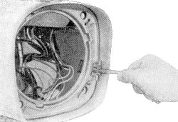
Fig. 22. Removing the headlamp insert
|
(by means of the hook that is in the service tool kit) until they hook in
externally. This frees the insert and it can be taken out. Glass and reflector are glued
to each other; please do not separate them unnecessarily.
The electric terminal board (1) is to be pulled off cautiously in order not to deform the
contact studs otherwise there will be no through current any mor. If the earth connection
(2) does not make proper contact the headlamp will not burn at all. On taking the retaining
spring (3) out of the three grooves of the lamp socket the bilex bulb jumps out, since a
tension spring is placed under it.
|
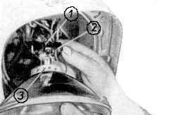
Fig. 23. Replacing the bilux bulb
|
Reassembly is performed in the reversed sequence of operation. Make sure
that the small plate tongues of the lamp socket are placed in the recess provided in the
reflector for this putpose.
Please handle the bilux bulb with a clean cloth or tissue paper, even clean fingers leave
traces of grease that will evaporate when the headlamp is burning and this will dim both
glass and reflector.
|
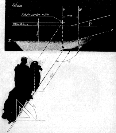
Fig. 24. Focussing diagram for asymmetric low beam
Schirm - SCREEN
Scheinwerfer-Mitte - HEAD LAMP CENTRE
Obere Grenze - UPpER LIMIT
6.12. Readjusting the asymmetric low beam
nächster Punkt ; Index
To prevent dazzling oncoming traffic, the asymmetric low beam is to be
adjusted with care.
Place the 'ES' at right angles to and in front of a vertical wall at a distance of 10
metres. Check the low beam with a track alignment gauge and a set square in conformity
with
|
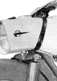
Fig. 25. Head lamp focussing
|
Fig. 24 The machine is to be loaded with the rider; the
rear telescopic forks should be placed at 'soft'. With this load, the light dark limit of
the beam of light should be 25 cm. under the headlamp centre 'Z' line and the break between
'V' and 'W'.
As a counter test, place the rear telescopic forks in position 'hard' and load the machine
additionally with the pillion rider. With this load the light dark limit may not be above
the admissible ultimate value (upper limit). After loosening the screws shown in fig.
25 the low beam can be readjusted.
6.13. Very important: the condition of the spark plug
nächster Punkt ; Index
The spark plug is subject to high thermal stresses. At first on combustion
at temperatures over 2,000 �C, then by the cool fresh gases and at the same time by the
combustion
|
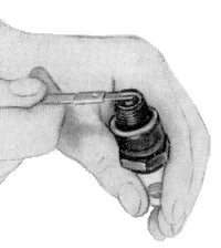
Fig. 26. Checking the spark plug electrodes
|
pressure of more then 30 atm. and all that 5,000 times and more per minute.
We assist the spark plug to do its job by checking and correcting the gap between the earth
and the centre electrode at least every 2,000 km.
The setting gauge of 0.6 mm. is in the service tool kit. To make a really good job of
adjusting the gab, file between the electrodes with a thin file until they are both flat
and all oxidation has been removed. If the electrodes are then closed up until a gap of
0.6 mm. between them is reached, the spark plug will be almost like new - because scale
and oxide on the electrodes has an insulting effect.
By the condition of the spark plug it can be easily seen, whether the engine is operating
perfectly or not. According to how the machine is handled the spark plug insulator colour
will be from white (riding with throttle wide open) to light fawn (slow riding and city
riding).
Molten metal beads on the spark plug insulator indicate that the carburettor adjustment
is too lean; the slow running needle is to be adjusted one notch higher.
However there may be other causes e.g. the gauze filter of the fuel shut-off cock may be
dirty or the vent hole in the filter cap may be clogged, wrong ignition timing, etc.
In any case the trouble must be remedied before serious damages, e.g. seizing of piston,
result.
A too dark spark plug apperance means that the engine is getting too much fuel; the slow
running needle must be lowered one notch. Though this is not as dangerous as an adjustment
which is too lean, the adjustment should still be corrected. Otherwise the muffler will be
clogged within a short time and the required engine power cannot be achieved.
Observe the condition of the spark plug very closely - this is best done with a
magnifying glass so that a grey-blue coloured spark-plug insulator baked by continous
overheating will not be taken for a dark spark plug condition and the already lean
carburettor adjustment set still leaner. It is assumed that the specified spark plug
'Isolator' M 14/260 is used, when estimating the condition of the spark plug. Under no
condition are hot plugs to be used. (This also applies in winter.)
Use 'Isolator' spark plugs if possible, Some other makes have a substantially lower thermal
value in spite of the same characteristics. Always replace the spark plug every 10,000 km.;
this expenditure will be repaid by easier starting.
The main function of the spark plug connector is the conduction of the high-tension
ignition current to the spark plug. In addition, the ceramic body shields the high
frequency radiations of the spark plug which would interfere with radio and TV reception
considerably. Whenever checking the spark plug always wipe out the inside of the socket
(moisture and oil), otherwise the ignition current will short across at this spot. Bend
the three clamping springs in such a way that they lie against the spark plug socket and
are earthed.
The interchangeable suppressor-capacitor is accessible after unscrewing the connector from
the ignition cable. Unscrew the threaded piece (now visible) with the small screwdriver and
the suppressor-capacitor will drop out. If the glass body is already slightly sooted or if
the metal parts are strongly corroded, the resistance-type suppressor is to be renewed.
Polish the contact points ot the spark plug connector as well; use a chip of wood for the
inside of the socket.
6.14. Chain lubrication; checking the chain slack; replacing the chain
nächster Punkt ; Index
With regard to lubrication the chain requires very little attention due to
the dustproof chain guards. Every 1,000 km. push back the chain tube on the rear chain
guard and apply 20 to 30 drops of oil to the chain while rotating the rear wheel.
Check the chain slack periodically every 1,000 km. Too much or too little slack results
in increased wear of both chain and bearings. Check the chain with the machine loaded;
the chain (not only the chain tube) must permit an upward as well as a downward movement
of 10 mm. Check the chain during one complete chain revolution. For chain readjust-
|
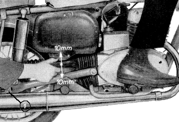
Fig. 27. Checking the chain slack
(1) Nut on flange bolt
|
ment, loosen the loating axle and nut on the flange bolt by one turn each.
The correct slack is established by uniformly turning the adjusting and counter nuts on
both chain tighteners.
After everything has been retightened, check slack once more while observing the proper
alignment of the wheels. Every fully floating machine has the unpleasant property of
immediately reacting with poor road-holding qualities, if the rear wheel is canted.
After approx. every 10,000 km. it is necessary to check the chain for wear. The master link
requires an extra thorough examination. The pins must not be loose in the link plate. If
the spring clip is loosely seated in the grooves of the pins then replace the master link.
The various chain makes have different pin diameters;please use an accurately fitting
master link.
After detaching the dynamo cover, the chain can be removed. The spring clip of the master
link is forced to the front (do not distort) with universal pliers and one end of the
chain is removed from the master link. An old but clean chain is fitted according to
instructions - with spring clip of course - and then original chain is removed.
For testing the chain, clean it thoroughly in cleaning spirit. If the individual link pins
are worn to such an extent that the chain, when held horizontally (edgewise) with both
hands is as curved as a 'scimitar', it should not be refitted. Within a short time the
spocket wheels will get 'shark's teeth'. A new chain is les expensive than the damage
caused by a possible chain fracture.
If you are satisfied that the chain is good for another few thousand kilometers, place it
in a bath of hot chain grease. In doing this observe the instructions of the manufacturers
on the grease tin.
When fitting, the cleaned and greased chain (oiled) is attached to the old one and pulled
through. Take good care that the spring clip is properly seated.
- This spring should be properly engarged in the groove and firmly seated.
- The open end of the flat spring should be opposite to the direction of rotation so
that it cannot be stripped off when running.
It is good practice to check the proper arrangement twice to be quite sure!
|
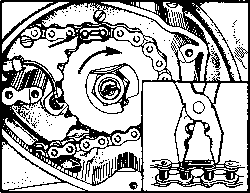
Fig. 28. Pushing the spring clip on the chain master link
6.15. Wheel alignment
nächster Punkt ; Index
Every fully swung machine is extremely sensitive to faulty wheel alignment.
With the rear-wheel misaligned even the 'ES' tends to float which may result in a 'belly
landing' when the roads are greasy.
Increased tyre wear will be another result.
After adjusting the chain or after mending a puncture always bend over and sight the front
tyre trough your legs, past the rear tyre. If you want to perform the job still more
accurately, take a measuring staff; the tyres should rest against the staff at 4 points.
|
Fig. 29. Wheel alignment
6.16. Cleaning and readjusting the brakes
nächster Punkt ; Index
The performance of every machine is no better than its brakes. You can
rely on the brakes of your 'ES'! However, it is indispensable to adjust the brakes
properly.
The clearance of the front wheel brake is adjusted so that the brake shoes touch, when the
end of the brake hand lever on the handle bars is still at a distance of approx. 50 mm.
from the throttle twist-grip (Fig. 14). Readjustment is performed on
the hand brake lever by turning the knurled-head screw.
After loosing the clamping screw, the lever itself is turned in such a way that the
stretched hand lies comfortably on the hand brake lever in extending the outstretched
arm (without having to flex the hand).
The clutch hand lever is naturally reset in the same way. Only in this way can greater
distances be covered without getting tired or can you react quickly when unexpected
obstacles turn up.
The foot brake lever is to be adjusted with the wing nut on the brake rod so that the
tip of your foot can rest on the brake pedal - so to speak in 'creeping position'.
Clean both brakes thoroughly every 5,000 km. Remove the abrasion, rechamfer the brake
linings on the brake-drum side and grease the fulcrum pins and brake spanners with
viscous grease.
Before disassemling mark the brake shoes in order that they will be re-mounted in their
former positions to which they were already adapted.
6.17. Telescopic forks
nächster Punkt ; Index
Maintenance of the telescopic forks is restricted to cleaning. Piston
and bottom valve are adjusted to the necessary damping value in special testing apparatus.
Uncontrollable manual readjusting achieves little success. The sectional view shows how
many parts the perfect performance is dependent on.
Please refer to your MZ service station who's personnel will give you the address of the
repairshop for telescopic forks or of its receiving depots.
|
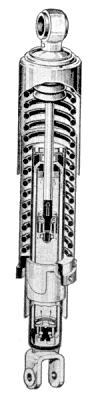
Fig. 30. Cross section of telescopic fork
6.18. Readjusting the stop light contact
nächster Punkt ; Index
Every readjustment of the rear wheel brake requires readjustment of the
stop light contact.
Remove the rubber socket with wire plug and loosen the counter nut by means of the open
ended spanner. An assistant should depress the brake pedal until the brake shoes are just
dragging while rotating the rear wheel.
|
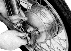
Fig. 31. Readjusting the stop light contact
|
The pedal is held in this position and the slotted screw is turned until
the stop light comes on (switch on ignition). Carefully tighten the counter nut in order
not to damage the insulating bush.
6.19. The proper tyre pressure
nächster Punkt ; Index
If you wish your tyres to last, then follow our instructions on tyre
pressure very strictly:
| front, with or without pillion rider | 1.4 atm. gauge pressure |
| rear, without pillion rider | 1.9 atm. gauge pressure |
| rear, with pillion rider | 2.1 atm. gauge pressure |
| rear, with sidecar and pillion rider | 2.6 atm. gauge pressure |
As previously mentioned, the toe-cap of your shoe is no measuring
instrument. Buy yourself a pressure gauge so that nothing is left to chance. The correct
tyre pressure is not only important for their serviceable life it is also responsible for
good road holding; even a difference of 0.2 atm. gauge pressure is noticeable. Check the
tyre pressure before starting on a journey because the pressure in the warmed up tyres
increases during the ride through fast riding or heavy load. Consider this fact when
checking the tyre pressure en route and do not deflate!
Strong sun's rays, gasoline and oil shorten the service life of the tyres. Keep an eye
on this.
If the tyre pressure should decrease without any obvious reason, check the valve
core first:
Unscrew valve cap; moisten your finger and lightly touch the valve. If bubbles emerge,
the valve core is to be removed with the top portion of the valve cap and replaced.
Therefore, always have two spare valve cores in your tyre rapair kit.
6.20. Tyre mounting
nächster Punkt ; Index
Even if it proves to be a 'flat' (punctured tyre=, there is no reason to
worry. Removing the tyre is very easy due to the fully floating axle.
Front wheel:
Loosen the nut of the fully floating axle and pull the axle out (drift of 8 mm. in service
tool kit). Always put axle and nut on the tool kit bag in order to keep the axle a fully
floating one. If reinstalled with road dirt, the next time you will need a hammer to
remove the axle. The wheel drops out forward; hang the brake over on the Bowden cable
above the front swinging fork.
|
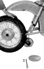
Fig. 32. Dismantling the front wheel
|
Rear wheel:
Remove stop light cable plug; loosen the wing nut with tension spring from the brake
rods; unscrew the floating axle and the brake back stop screw and put them on the tool
bag together with the distance piece.
Now the rear wheel is pulled from the drive (three driving pins in damping rubber) and
put down in the manner shown in fig. 33. In this position the brake
back stop (arrow) can be pulled out backwards. Now the rear wheel is to be pulled out
backwards to the left.
Replacing the wheel is performed in the reverse sequence of operation. Particular
attention must be paid to inserting the three driving pins in the corresponding bores
of the damping rubber.
|
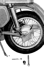
Fig. 33. Rear wheel pulled off from the drive
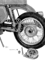
Fig. 34. Removing the rear wheel
Telescopic fork adjustment (1) soft (2) hard
|
If you tackle tyre fitting in the proper way, changing the inner tube is
no problem. First of all remove the valve nut and screw out the valve core. Place the
wheel flat on the ground (with a rag underneath) and push the tyre from the entire
circumference of the rim.
|
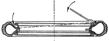
Fig. 35. Tyre fitting
|
Pleasenote as a definite rule:
Inner tube first out at the valve and last in at the valve.
Force the tyre into the well opposite the valve with both tips of your feet so that the
bead slips into the well.Now the bead of the tyre can be lifted over the rim flange with
the tyre levers a the right and the left of the valve.
After the inner tube has been taken out, inspect the inside of the tyre to find the cause
of the puncture and remove it. Inflate the spare tube slightly to prevent its wrinkling
in the tyre. Apply some talcum powder to the inside of the tyre and refit it in the
reversed sequence of operation. Do not use brute force, for it the bead of the tyre is
properly seated in the drop-base without the inner tube being clamped underneath, it will
go on without great effort.
With the inner tube half inflated, make sure that the check line of the tyre is at an
equal distance from the rim flange, so that it runs perfectly true (roadholding).
If a spare inner tube is not available, use the tyre repair kit. Directions for use are
enclosed
6.21. Removing the residues of combustion
nächster Punkt ; Index
If, after approx. 10,000 km. you are of opinion that the engine performance
has slightly decreased despite correct carburettor adjustment and ignition timing, it will
be necessary to check the exhaust duct for residues of combustion. Loosen the clamping
ring nut on the cylinder with the 14 mm. socket wrench (service tool kit) and unscrew the
mounting clips of the muffler at the flexible engine mounting in the front and the tie rod
at the rear.
If you have followed our recommendations regarding riding style, fuel and lubrication, you
will find only negligible quantities of residues in the exhaust port. In this case, tube
and silencer are refitted. However, if the exhaust port is heavily clogged by carbonaceous
oil deposit, the combustion chamber is to be decoked as well. Remove the cylinder head and
scrape it out with a wire brush or emery cloth until the metal is clean.
Now the piston: place it at top dead centre and only remove the loose scale-like
carbonaceous oil deposits from the piston head with the wire brush. Do not remove the
baked layer of deposits since it protects the piston against excessive thermal absorption.
(by the way - should you ever hold the piston in your hands: do not remove the carbonaceous
oil deposits from the piston ring and piston skirt; merely scratch out the piston ring
grooves with due care.)
To clean the exhaust port, place the piston at bottom dead centre and block the two
transfer ports with a small and clean piece of cloth. The chips of oil carbon are very
hard and might cause trouble between piston and cylinder. The exhaust port is scraped
out from the outside through the exhaust duct.
|
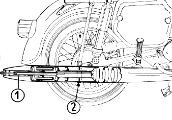
Fig. 36. Cross section of silencer
- pitot tube
- Disconnecting point
|
Blow out (rubber hose) any carbonaceous oil deposits which have dropped
into the piston. Cleaning the exhaust manifold is not necessary because the baked layer
of carboneous oil deposits in the pipe acts as a heat insulator. With normal operation,
no residue will be deposited in the front portion of the silencer. In the end piece,
however, in the annular clearance between pitot tube (1) and silencer piece, a viscous
oil sludge from the cooled-down combustion gases will be deposited.
After unscrewing the two hexagon nuts, the endpiece can be pulled off. The unrestricted
passage is re-established with a wooden chip or the like. Never use a welding torch for
cleaning the silencer; you would be shocked to see the bright chrome-plated parts becoming
as blue as a violet!
You will have more success if you use hot water and some dirt-solvent agent purchased at
the nearest store.
Resist the temptation of altering the silencer; its dynamic pressure is a component of a
whole system beginning at the air filter and ending at the tailpiece of the silencer. Any
alteration by removing parts will result in increased fuel consumption, reduced engine
power and more noise. In this case noise is waste energy.
7. 'ES' - cosmetic
nächster Punkt ; Index
The care that is applied to the beauty treatment your wife receives in a
beauty parlour, should be applied to your 'ES', in order to maintain its attractive
appearance over a long period of time.
If your motorcycle is dusty, never wipe off the dry dust but spray it first with a
polishing fluid. For cleaning and polishing, use soft rags only. Crusted dirt is to be
softened with water from a can or hose and then rinsed. Use soft brushes only.
The water jet should not be too strong, since this damages the paintwork too. Do not
direct the jet at the joints of the carburettor cover, brake hubs, etc. Should you use
bucket and sponge, rinse the sponge frequently and thoroughly in order not to scratch
the paintwork with dust particles.
After washing, dry and polish the paintwork immediately to prevent formation of water
stains. Water stains are difficult to remove. Spray the completely dry paintwork with
some polishing fluid of low silicone content (motorcar quickwashing fluid) and repolish.
If the engine should be heavily soiled, clean it with a cleaning spirit. Be careful not
to splash it on the paintwork; this will result in dull stains. Mind this when refilling!
Should the service station attendant be unaware of it, then tell him. Never clean the
saddle and the pillion seat with gasoline. It might destroy the preserving film and the
seats willlose colour. Use the same soap solution that your wife uses for her seamless
stockings: it will serve the purpose even better! You may also use this soap solution to
remove the fly specks from the headlamp glass.
When the 'ES' is shining again in all its original beauty, do not be contented. Check the
lighting in all switch positions. You may have torn off a loose cable while cleaning. Start
the engine by kick-starting it once, because a jet of water may have got into the wrong
place!
Remove any water in the brake drums by applying the brakes slightly during a short trial
run.
|
8. 'Mothballing'
nächster Punkt ; Index
If you want or are compelled to lay up your vehicle for a long period of
time, proceed in the following way:
- Clean the motorcycle thoroughly. Have the lower side and the inside of the mudguards
treated with a spray gun by the filling station attendant. Do not forget the air
filter and the intake muffler; they are to be thoroughly cleaned as well.
- Grease all lubricating points (lubrication chart, figures
37 and 38).
- Pour 0.2 litre of anti-corrosion oil KMO 2 T or, if not available, flushing oil as a
preservative through the sparkplug hole into cylinder. It is good practice to till in
first 0.1 litre, then screw in an unserviceable spark plug and kick the starter over
slowly several times (without switching on the ignition) to allow the
anti-corrosion oil to reach all bearing positions.
Finally the rest of the oil is poured in with the piston resting at bottom
dead centre.
An engine preserved in this way may not be test started but only kicked over once now and
again. Not until dormancy has ended and the riding season begins again, the spark plug is
removed and the starter kicked over several times. This forces the anti-corrosion oil out
of the outlet port and the spark plug hole. Then start in the usual way but with a little
more acceleration than usual to avoid fouling up the sparkplug due to the excess of oil.
- Remove the battery and entrust it to the care of an electric service station.
- Fog-spray the entire machine thoroughly.
- Place the jacked-up machine in a dry room. Tzhe wheels should not touch the ground.
Reduce the tyre pressure to approx. 1/2 atm. gauge pressure. Cover the machine with
a canopy or collapsible garage.
9. Troubles - what to do?
9.1. First of all; the condition of the spark plug
nächster Punkt ; Index
If your 'ES' should stall without obvious reason or if the engine does not
start, check the spark plug first of all. The trouble may be caused by a shortage or an
excess of fuel.
Proceed systematically; first of all pull the fuel hose off the carburettor, open the fuel
shut-off briefly and check whether sufficient fuel is fed to the carburettor or no fuel at
all. It appears that half the engine was stripped down when in fact refilling hat been
forgotten!
9.2. Engine fails to start
(ignition is switched on)
nächster Punkt ; Index
Choke lever pulled out but the cold engine fails to start:
- Fuel shut-off cock is closed or not in position 'reserve'
- Filter or fuel shut-off cock is dirty
- Fuel feed pipe is blocked
- Vent hole in fuel tank filler cap is blocked
- Starting jet is blocked or throttle twist grip not closed
- Spark plug socket disconnected or resistor in radio shielding cap is defective.
Ignition is switched on but the red control light does not light up:
- Battery discharged (push-start the engine in second gear with switch in position 5)
- Battery cable is torn off
- Fuse is blown
- Defective ignition lock or ignition key is too short
Red control light lights up, carburettor is clean, nevertheless engine fails
to start:
- Fouled spark plug (resulting fromslow riding or too rich a mixture)
- Spark plug is wet (float needle leaky)
To a): Place the metal portion of the spark plug on a bare spot of the
engine (but by no means on the carburettor), switch on ignition and kick the starter. A
powerful spark should flash over at the electrodes. If not, replace the spark plug with
a new one which should be in the service tool kit.
To b): Close fuel shut.off cock, open throttle twist grip wide and turn the engine several
times with the kick starter. Screw in cleaned spark plug again and kick-start the engine.
Do not open the fuel shut-off cock until the engine is running again.
|
9.3. Red controllight fails to go out in spite of higher speed
nächster Punkt ; Index
- Regulator or dynamo defective
- Chafed insulation of cables in electric circuit (insulation tape)
- Sticking carbon brushes (wipe off or lengthen coil spring)
9.4. Engine runs erratically
nächster Punkt ; Index
- Choke lever stillpushed out though engine has warmed up
- Air filter heavily soiled
- Float needle leaky (worn or dirty)
- Main jet and pintle nozzle loose
- Leaky float and fuel filling the float
- Condenser breaks down (contact sparking)
9.5. Engine fails to respond to throttle
nächster Punkt ; Index
- Main jet is dirty
- Carburettor is loose
- Air filter missing
- Needle spring is broken; needle located before main jet
- Spark plug shorting across the insulator
|
9.6. Fuel consumption is too high
nächster Punkt ; Index
Before you annoy someone with the 'excessive fuel consumption' ride to
a carburettor service station first; at this station the carburettor can be perfectly
metered.
Perhaps you have filled up with some fuel of different octane rating and after the next
refilling the consumption will be normal again. When riding on the fuel consumption curve
of figure 3:
between 60 and 70 km.p.h. your engine will consume approx. 3 litres, but with sustained
high speed, consumption increases to 5.5 to 6 litres! this is quite normal too, for:
fast riding costs fuel and consequently money! This ist not only the case with
MZ, but with all other motorcycles as well.
If your 'ES' should have an exceptionally high fuel consumption, though the machine is
mechanically in proper condition, check the following points:
- Main jet or pintle nozzle is loose
- Dry air filter too old or wet
- Seat of float needle is worn (more than 50,000 km.)
- Defective gasket on the tickling piston
If you cannot find anything, ride to a carburettor service station. In
fact, correct carburettor adjustment is a science to itself.
9.7. Battery fails to accumulate current
nächster Punkt ; Index
- The specific gravity of the electrolyte is not correct
- Level of the electrolyte is too low
- Plates are damaged
- Connecting cables losse or corroded
- Incorrect regulator adjustment
- Dynamo is charging insufficiently
9.8. Bulbs do not burn
nächster Punkt ; Index
- Bulb or socket oxidised
- Contact spring oxidised or does not seat properly
- Feed line disconnected or loose
|
Extra accessories
nächster Punkt ; Index
As extras the following accessories can be obtained from the MZ Sales
Depot for Spare Parts via our Authorized MZ Service Stations:
- Leg guard plates
In addition to an excellent mud protection for the rider a better cooling air
supply to the cylinder is achieved by air guide plates on both sides. Even with
continuous operation the cylinder will keep its normal operating temperature.
- Luggage carrier (case carrier)
is suitable for light hand-luggage - heavy cases affect the steering stability.
Spare parts procurement
nächster Punkt ; Index
If you need spare parts for your 'ES', contact the nearest MZ Service
Station or a special MZ Sales Depot. We cannot supply you with spare parts directly.
Our customers abroad should contact exclusively the importer of the country in
question for spare parts and in case of warranty claims.
After sales service
nächster Punkt ; Index
Our MZ Service Stations are obliged to advise you on all technical
problems. Whenever you should write directly to VEB Motorradwerk Zschopau because you
are of opinion that you have not been satisfactorily attended to, address your letter
exclusively to the Department 'Kundendienst'. In case of enquiries on technical problems,
be sure to indicate chassis and engine serial numbers. If it is a matter of engine output
and fuel consumption, please inform us of the carburettor adjustment, road performance
and the condition of the spark plug to enable our 'Kundendienst' to give you satisfactory
advice!
|
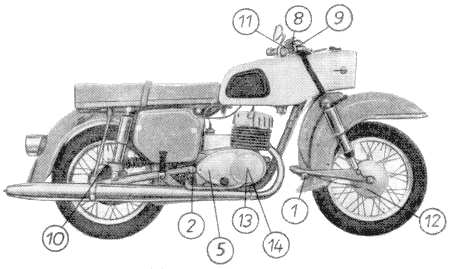
Fig. 37. Lubricating points
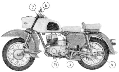
Fig. 38. Lubricating points
Lubrication chart
nächster Punkt ; Index
| No. | Lubrication point | Number | Lubricant |
| | 5 Lubrication points for high pressure grease gun | |
| 1 | Suspension arm, front | 1 | motor oil GL 60 |
| 2 | Suspension arm, rear | 1 | motor oil GL 60 |
| 3 | Brake pedal shaft | 1 | high melting point grease |
| 4 | Brake spanner, rear | 1 | motor oil GL 60 |
| 5 | Speedometer drive | 1 | lubricating grease |
| | Lubricate with oil can | |
| 6 | Hand brake Bowden cable | | motor oil GL 60 |
| 7 | Clutch Bowden cable | | motor oil GL 60 |
| 8 | Throttle Bowden cable | | motor oil GL 60 |
| 9 | Bowden cable for tickling piston | | motor oil GL 60 |
| 10 | Chain | | motor oil GL 60 |
| | Lubricate with grease | |
| 11 | Twist-grip slide valve | | automative grease |
| 12 | Brake spanner, front | | high melting point grease |
| 13 | Cam bearer | | high melting point grease |
| | Hypoid gear oil | |
| 14 | Grease felt on contact-breaker cam | | Hypoid gear oil |
| | Oil change | |
| 15 | Gearbox | | 750 cu.cm. motor oil GL 60 |
Maintenance chart GL 60
nächster Punkt ; Index
Engine and gearbox
Before each trip:
Check free play of clutch, readjust if necessary (clearance on hand lever 3 to 4 mm.)
After every 500 km.:
Change gear oil (drain off the oil, flush with flushing oil, fill up with 750 cu.cm. motor
oil GL 60); each further oil change after every 20,000 km.
After every 1,000 km.:
Check gear oil (oil should flow out of the inspection hole)
Air filter: knock the dust out of the paper filter element.
After every 2,500 km.:
Check all screws of the engine for tightness (if required - retighten)
After every 5,000 km.:
Fuel shut-off cock (remove, disassemble, clean and reassemble)
Exhaust system (disassemble and clean)
Carburettor (clean, retighten screw connections and pintle nozzle)
(check gaskets and
slow running needle)
Intake muffler (dismantle and clean)
Ignition system and lighting
Before each trip:
Lighting, horn and stop lights (check and readjust if required)
After every 2,000 km.:
Check sparkplug (clean and set gap at 0.6 mm.)
Contact breaker (contact breaker points' gap 0.3 mm.; apply 2 to 3 drops of Hypoid oil to
grease felt)
Battery (check level of elekrolyte - if necessary clean battery box with warm water.)
After every 5,000 km.:
Grease the cam bearer with Ceritol high melting point grease
Check cable connections for corrosion (do not patch up the fuse)
After every 10,000 km.:
Replace spark plug (Isolator M 14/260)
Frame
Before each trip:
Check the brakes and readjust them if necessary.Make a brake test before starting on a trip.
Tyre pressure (atm. gauge pressure)
solo: front 1.4 atm. with pillion rider: front 1.4 atm.
solo rear 1.9 atm. with pillion rider: rear 2.1 atm.
After every 1,000 km.:
Chain tension (check the slack, readjust if necessary)
Check the brakes and readjust if necessary. Make a brake test before starting a trip.
Check all screws of the chassis and both floating axles for tight seating.
After every 2,500 km.:
Steering bearing (take up the play by readjusting)
|
| Lubrication points of the chassis |
| After every 2,500 km.: |
| Front swinging fork | motor oil GL 60 | lubricate |
| Rear swinging fork | motor oil GL 60 | lubricate |
| Brake spanner, rear | motor oil GL 60 | 2 or 3 strokes with oil filled grease gun |
| Hand lever | motor oil GL 60 | 1 or 2 drops with the oil can |
Driving chain
(gear, rear-wheel) | Getriebeöl GH 60 | push back chain tube, lubricate while rotating the rear wheel |
| Speedometer drive | automative grease | 2 or 3 strokes with grease gun |
| Bowden cables | motor oil GL 60 | remove Bowden cables and oil |
| After every 5,000 km.: |
| Brake spanner, front | high melting point grease | remove, clean and grease |
| Brake pedal shaft | motor oil GL 60 | dismantle, clean and reassemble with high melting point grease |
| After every 10,000 km.: |
| Speedometer cable | motor oil GL 60 | remove and oil |
| Steering bearing | high melting point grease | remove, clean and apply fresh grease |
Wheel bearings,
front and rear | high melting point grease | dismantle, clean and apply fresh grease |
| Twist-grip slide valve | high melting point grease | dismantle and apply fresh grease |
Driving chain
(gear, rear wheel) | | Remove chain, wash it, check it for wear and treat it in hot chain grease. |
Fig. 39. Wiring diagram
- Flashing light indicator, right
- Flashing light indicator switch
- Condenser
- Earth
- Dynamo LMZ FR 6/60
- Contact breaker cam
- Cut-out
- Stop light switch
- Combined tail, brake and licence plate light
- Battery
- Fuse box
- Regulator
- Ignition coil
- Flashing light indicator, left
- Dimmer switch with horn push button and by-pass light signal button.
- Headlamp
- Low beam
- Parking light
- High beam
- Combined ignition and lighting switch
- Blinker unit
- Speedometer
- Control lights
- Speedometer lighting
- Horn
- Spark plug
- For position 5
| sw | = black |
| rt | = red |
| gn | = green |
| ws | = white |
| ge | = yellow |
| gr | = grey |
| bl | = blue |
| br | = brown |
Index