

|
Index Dear friend of MZ, "Bon voyage"! Table of Contents1. Technical Data 1.1. Engine and Power Transmission 1.2. Carburetter 1.3. Cycle Parts 1.4. Electrical Equipment 1.5. Masses 1.6. Capacities 1.7. Road Performances 2. Fuel, Lubricants etc. 3. Operation 3.1. Controls 3.2. Starting and Driving 3.3. Information for Running-in 4. Maintenance 4.1. General Instructions 4.2. Maintenance Chart 4.3. Lubrication Points 4.4. Gearbox Lubrication 4.5. Clutch and Brakes 4.6. Fuel Feed, Carburetter, Induction System 4.7. Wheels and Tyres 4.8. Rear Wheel Drive 4.9. Electrical Equipment 4.10. Information about Winter Operation 5. Faults and Their Remedies 6. After-sales Service 7. For Making the Motor-cycles Complete 8. Fresh-oil Dosing Device Wiring diagram (fold-out plate) 1. Technical Data1.1. Engine and Power Transmissionnächster Punkt ; Index |
| Type of engine | EM 125 | EM 150.2 | EM 150 |
| Cycle | |||
| Output | 7.5 kW at 6,000 rpm | 9 kW at 6,000 rpm | 10.5 kW at 6,500 rpm |
| Maximum torque | 12.3 Nm at 5,500 rpm | 15 Nm at 5,500 rpm | 15.8 Nm at 6,200 rpm |
| Lubrication | |||
| Gearbox | |||
| Number of speeds | 5 | 5 | 5 |
| Idling tell-tale light | |||
| Power transmission to rear wheel | |||
| Roller chain | |||
| Transmission gearbox - rear wheel | 3.2 (15:48 teeth) | 3.0 (16:48 teeth) | 3.2 (15:48 teeth) |
| Type | 22 N 2-2 | 24 N 2-2 | 24 N 2-2 |
| Suction pipe diameter | 22 mm | 24 mm | 24 mm |
| Main jet | 100 | 120 | 120 |
| Needle jet | 70 2) | 70 2) | 70 2) |
| Partial load needle | 2,5 A 513 | 2,5 A 513 | 2,5 A 513 |
| Partial load needle position from top | 3 1) (2 after running-in) | 3 1) (2 after running-in) | 3 1) (2 after running-in) |
| Starting jet | 70 | 70 | 70 |
| Idling jet | 40 | 40 | 40 |
| Idle air adjusting screw | for about 1.5 revolutions open, but adjustment of the maximum concentration of CO in exhaust gas to 2.5 to 3.5 per cent by volume at 1,200 rpm | ||
| 1) Pay attention to the sparking-plug appearance! The lower plate of the needle holder counts! | |||
| 2) with 2 compensator tack-type jets 60 | |||
| Springing | |||
| front | telescopic fork with hydraulic damping, spring deflection 185 mm | ||
| rear | suspension units with hydraulic damping, spring deflection 105 mm, spring pre-load and setting angle adjustable | ||
| Wheels | |||
| Rims | |||
| front | 1.60 x 18 | 1.60 x 18 | 1.60 x 18 |
| rear | 1.85Bx16 | 1.85Bx16 | 1.85Bx16 |
| Tyres | |||
| front | 2.75 x 18 | 2.75 x 18 | 2.75 x 18 |
| rear | 3.25 x 16 | 3.25 x 16 | 3.25 x 16 |
| Tyre inflation pressure (gauge pressure) | |||
| Solo | |||
| front | |||
| rear | |||
| with permissible total mass | |||
| front | |||
| rear | |||
| Brakes | |||
| front | hydraulically actuated disk brake | ||
| rear | |||
| Rated voltage | 12 V | 12 V | 12 V |
| Ignition | 2.5 +0.5 mm (22°45' to 23°45') before top dead centre, | ||
| Ignition timing | invariable | ||
| Contact-breaker gap | 0.3 +0.1 mm (closing angle 132° + 5° in idling) | ||
| Sparking-plug | Isolator ZM 14-260 or comparable foreign types (multi range plugs) | ||
| Electrode gap | 0.6 mm | 0.6 mm | 0.6 mm |
| Three-phase current dynamo | three-phase current 14 V, 15 A with rectifier and regulator | ||
| Battery | 12 V, 5.5 Ah | 12 V, 5.5 Ah | 12 V, 5.5 Ah |
| Electric bulbs | |||
| headlamp | 12 V, 45/40 W, TGL 11413, or H 4, passing beam asymmetric | ||
| parking light | 12 V, 4 W, cap BA 9 s, TGL 10833 | ||
| tail light | 12 V, 5 W, cap BA 15 s | ||
| stop light | 12 V, 21 W, cap BA 15 s | ||
| flashing light | 12 V, 21 W, cap BA 15 s | ||
| control lamps and instrument lighting | 12 V, 2 W, cap BA 7 s, TGL 10833 | ||
| Fuses | |||
| main fuse | 2 x fuse link A 16 TGL 11135 (16 A) | ||
| flashing-light direction indicator system | fuse link A 4 TGL 11135 (4 A) | ||
| dynamo excitation | fuse link T 2 A (miniature fuse 2 A) | ||
| Empty mass (with fuel and tools) | 118 kg 1) 120 kg 2)118 kg 1) 120 kg 2) | 118 kg 1) 120 kg 2) | |
| Permissible total mass | 290 kg | 290 kg | 290 kg |
| 1) Variant with drum brake | |||
| 2) Variant with disk brake | |||
| Fuel tank | 13 l | 13 l | 13 l |
| including reserve of | 1.5 l | 1.5 l | 1.5 l |
| Gear oil | 0.5 l | 0.5 l | 0.5 l |
| Maximum speed | 100 km/h | 105 km/h | 110 km/h |
| depending an load, atmospheric conditions and sitting position | |||
| Fuel consumption | 2.3 to 3.5 l/100 km | 2.4 to 3.6 l/100 km | 2.6 to 4.0 l/100 km |
2. Fuel, Lubricants etc.nächster Punkt ; IndexEnginePetrol having an octane rating of 88 (ROZ) which is mixed with
two-stroke engine oil in the ratio of 50:1. GearboxGear oil SAE 80 or non-additive type of engine oil SAE 40 for summer and winter. In the GDR, oil of grade GL 100 is used. Cycle partsGear oil SAE 80 and antifriction bearing grease. Electrical equipmentFor a new battery use accumulator sulphuric acid having a density of
1.28 g/cm3 (in the tropics 1.23 g/cm3) at 25 °C. For topping up
the battery, only use distilled water. Use grease battery terminals for protection
against corrosion of the battery connections. 3. Operation3.1. Controlsnächster Punkt ; IndexFigs. 1 to 9 show all control elements required for operating the motor-cycle and their functions. Please, familiarise yourself with them throughly before the first start. |

Fig. 1. Controls of the motor-cycle
| (1) | Ignition and light switch |
| (2) | Clutch lever |
| (3) | Combined switches for electrical system |
| (4) | Gearchange pedal |
| (5) | Fuel shut-off cock |
| (6) | Kick-Starter |
| (7) | Prop stand |
| (8) | Hand brake lever |
| (9) | Lever for cold-starting device |
| (10) | Throttle twist-grip |
| (11) | Brake pedal |
| (12) | Pillionist's foot rests |

Fig. 2. Instruments (standard design)
| (1) | Ignition and light switch (switch positions as shown in Fig. 3) |
| (2) | Speedometer with kilometer counter |
| (3) | High-beam headlight indicator (blue) |
| (4) | Tell-tale light for dynamo and flashing-light direction indicator system (green) |

Fig. 3. Instruments (deluxe model)
| (0) | All loads switched off - key (9) can be withdrawn |
| (1) | Parking position at night - key can be withdrawn, town light switched on |
| (2) | Ignition switched on, riding in the daytime - key cannot be withdrawn - pushing the motor-cycle for starting without battery is possible with the 2nd gear in engagement |
| (3) | Ignition switched on, parking and tail lamps burn - key cannot be withdrawn |
| (4) | Ignition switched on, night operation - key cannot be withdrawn |
| (5) | Revolution counter |
| (6) | Idling indicator (yellow) |
| (7) | Control light for dynamo (red) |
| (8) | Ignition and light switch |
| (9) | Ignition key |
| (10) | High-beam headlight indicator (blue) |
| (11) | Tell-tale light for flashing-light direction indicator system (green) |
| (12) | Speedometer with kilometer counter |

Fig. 4. Combined switches at handle-bars
| (1) | Dimmer switches for headlamp |
 | high-beam headlight |
 | passing beam |
| (2) | Switch for direction indication |
| (L) | left-hand flashing-light indicator |
| (R) | right-hand flashing-light indicator |
| (3) | Push-button for horn |
| (4) | Push-button for by-pass light signal |

Fig. 5. Throttle twist-grip and cold-starting device
| (1) | Cold-starting device closed |
| (2) | Cold-starting device switched on |
| (Z) | Throttle twist-grip closed |
| (A) | Throttle twist-grip open (full throttle) |
| (B) | Friction brake throttle twist-grip - adjusting screw |

Fig. 6. Fuel shut-off cock
| (1) | Fuel shut-off cock closed |
| (2) | Fuel shut-off cock open |
| (3) | Reserve position |
| (F1) | Inlet filter |
| (F2) | Outlet filter |

Fig. 7. Gearchange pedal
Numbers: position of the gears
| (F) | Gearchange pedal |
| (K) | Kick-starter |

Fig. 8. Theft prevention (at the right in Fig. 8. Special version for export)
| (1) | Sense of rotation for unlatching the look |
| (2) | Sense of rotation for latching the look |
The theft prevention device has to be locked after unlatching by shifting the lock upwards (to the interior in the export design).

Fig. 9. Changing the pre-load on the spring
| (1) | Setting for single-person operation |
| (2) | Setting for higher loads |
| (3) | Fastening point for 'soft' springing |
| (4) | Fastening point for 'harder' springing |
3.2. Starting and Drivingnächster Punkt ; IndexBefore any ride, check the vehicle for reliability of operation and
roadworthiness according to the Maintenance Chart (see Section 4.2.).
Notice! In the case of extremely low ambient temperatures, and
when the engine has been subjected to several starting trials in vain, allow the engine
to rest for 20s in order that fuel in the cold-starting device can be restored to normal
level. |

Fig. 10. Engine speed and travel speed ranges of ETZ 125
 | Maximum engine speed and travel speed during the running-in period |
 | Main operating ranges (engine speed and travel speed) after the running-in period |

Fig. 11. Engine speed and travel speed ranges of ETZ 150
 | Maximum engine speed and travel speed during the running-in period |
 | Main operating ranges (engine speed and travel speed) after the running-in period The extension of the ranges shown in black applies to the ETZ 150 with an output of 10.5 kW |
|
Braking |
3.3. Information for Running-innächster Punkt ; IndexA distance of 1,500 to 2,000 km is considered as running-in period for the engine. During this time, observe the following information.
4. Maintenance4.1. General Instructionsnächster Punkt ; IndexThe tool kit accomodated under the right-hand side panel enables you to
perform almost all maintenance operations according to the Maintenance Chart. Take the
Guarantee Regulations into consideration. |

Fig. 12. Battery and tool accomodation
| (1) | Tool kit | (4) | Top edge of plate |
| (2) | Flasher unit (in foamed plastic pocket) | (5) | Electrolyte level |
| (3) | Fuse box | (6) | Oil filling opening |
| A = 5 mm (level of electrolyte an top of plate) | |||
4.2. Maintenance Chartnächster Punkt ; Index |
| Maintenance operations | |||||||
| before a ride | after a ride | after 500 km | every 2,500 km | every 5,000 km | every 10,000 km | every 20,000 km | |
| Engine and gearbox | |||||||
| Check the clutch clearance | |||||||
| Check the gear oil level | |||||||
| Change the gear oil | |||||||
| Retighten the exhaust pipe mounting at the cylinder (93 Nm) | |||||||
| Check the engine fastening screws for tight fit | |||||||
| Clean the carburetter, retighten the mounting of the individual parts | |||||||
| Check the carburetter tuning | |||||||
| Checking the emission of noxious substances according to the values determined by law | |||||||
| Electrical equipment | |||||||
| Check the lighting and signalling systems for proper functioning | |||||||
| Check and adjust the sparking-plug | |||||||
| Replace sparking-plug by a new one | |||||||
| Check the contact-breaker gap | |||||||
| Check for advanced ignition | |||||||
| Apply three drops of Hypoid oil to the lubricating felt pad of contact-breaker cam | |||||||
| Check the level of the electrolyte in the battery | |||||||
| Cycle parts | |||||||
| Check the brakes for proper functioning | |||||||
| Check the brake fluid level in the reservoir | |||||||
| Change the brake fluid | every two years | ||||||
| Check the thickness of lining an brake shoes (disk brake) | |||||||
| Wipe the guide tubes of the telescopic fork (model with protective cap) | |||||||
| Telescopic fork - inspection for leaks | |||||||
| Check the tyre inflation pressure | |||||||
| Check amount of fuel in fuel tank | |||||||
| Dismantle the fuel shut-off cock, clean the filter | |||||||
| Clean the air filter by tapping | |||||||
| Wipe the air filter bowl | |||||||
| Replace the air filter by a new one | |||||||
| Check all accessible screwed connections for tight fit | |||||||
| Driving chain- check the sag | |||||||
| Lubricate the driving chain | |||||||
| Lubricate the hand levers and throttle-twist grip | |||||||
| Dismantle the cable controls and oil them | |||||||
| Oil the drive shafts for speedometer and revolution counter | |||||||
| Dismantle the brake shoes at the front and rear, the brake cam at the front; clean and lubricate the points of support | |||||||
| Lubricate the rear brake cam | |||||||
| Clean and lubricate the wheel bearings | |||||||
| Check the swing-arm bearing and the springing | |||||||
|
Have the faults removed that you found during the maintenance. x¹ On the occasion of the 1st and 2nd inspection under guarantee 4.3. Lubrication Points (Figs. 13 and 14)nächster Punkt ; Index
| |||||||||||||||||||||||||||||||||||||||||||||||||||||||||||||||

Fig. 13. ETZ 125/150 - View from the right (For explanation of the legends see Section 4.3.)

Fig. 14. ETZ 125/150 - View from the left (For explantation of the legends see Section 4.3.)
4.4. Gearbox Lubricationnächster Punkt ; IndexChecking the oil level |

Fig. 15. Oil checking screw and oil drain screw plugs
| (1) | Oil checking screw |
| (2) | Oil drain screw plug for clutch compartment |
| (3) | Oil drain screw plug for gearbox |
| (4) | Idle gear detent - do not screw out ! |
Arrow: Level of oil in gearbox
|
Oil change 4.5. Clutch and Brakesnächster Punkt ; IndexClutch |

Fig. 16. Adjusting the clutch (also mechanical brake) at the hand lever
| (1) | Adjusting screw with check nut |
| (S) | Clutch clearance |
|
lution. Then screw down the adjusting screw until the stop can just be felt and then slacken it back through 3/4 of a revolution. Then fix this setting by means of the lock nut. |

Fig. 17. Rough adjustment of clutch
| (1) | Adjusting screw and lock nut |
| (2) | Covering cap |
|
Mechanical brakes
|

Fig. 18. Adjusting the rear wheel brake and stop-light switch
| (1) | Adjusting nut of rear wheel brake |
| (2) | Connection cable |
| (3) | Setting screw |
|
Disk brake |

Fig. 19. Adjusting the stop light switch
| (1) | Stop light switch, front |
| (G) | Jointed piece |

Fig. 20. Replacement at the brake shoes
| (1) | Brake shoes |
| (2) | Return spring |
| (3) | Fastening bolt |
| (D) | Minimum thickness of brake lining (0.5 mm) |
4.6. Fuel Feed, Carburetter, Induction Systemnächster Punkt ; IndexThe fuel is cleaned in the fuel shut-off cock whose filter
(F2) (Fig. 6) can be cleaned after unscrewing the filter
bowl. The Filter (F1) (Fig. 6) in the fuel tank is only
accessible when the fuel shut-off cock is unscrewed. |

Fig. 21. Carburetter 22 N 2-2 or 24 N 2-2
| (1) | Clamping ring with screw |
| (2) | Fuel feed |
| (3) | Screwing of the cold-starting device with adjusting screw |
| (4) | Adjusting screw for throttle - cable control |
| (5) | Locking nut |
| (6) | Clamping screw |
| (7) | Stop screw for throttle valve |
| (8) | Idling air adjusting screw |
|
(7). For cleaning the carburetter, dismantle it in the order 1 to 6
(Fig. 21). |

Fig. 22. Removing the air filter - position of fuses
| (1) | Cover for filter bowl | (3) | Battery holder |
| (2) | Screwing | (4) | Flasher unit |
| Position of the fuses: | |||
| (1) | Generator (T 2 A) | (3) | Main fuse (16 A) - positive line |
| (2) | Direction indicator (4 A) | (4) | Main fuse (16 A) - negative line |

Fig. 23. Seat of air filter in filter bowl
4.7. Wheels and Tyresnächster Punkt ; IndexRemoval and fitting the front wheel |

Fig. 24. Removing the front wheel (drum broke)
| (1) | Axle nut |
| (2) | Fastening of the abutment brace |
| (3) | Clamping screw |

Fig. 25. Removal of rear wheel, 1st stage
|
Removal and fitting of the rear wheel |

Fig. 26. Removal of rear wheel, 2nd stage
|
Changing tyres and inner tubes |

Fig. 27. Arrangement dog - damping rubber
| (1) | Dog |
| (2) | Dog accomodation in damping rubber |
|
Then remove the inner tube. Before putting the new inner tube in place, check the interior of the tyre for foreign particles and damage; apply talcum to the new inner tube, put it in place and, starting from opposite the valve, fit the tyre. |
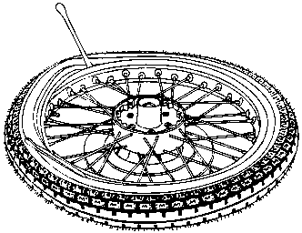
Fig. 28. Removal of tyre
|
Notice! |
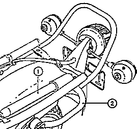
Fig. 29. Accomodation of the inflation pump
| (1) | Inflation pump |
| (2) | Handle for propping up the motor-cycle |
|
Care of the tyres 4.8. Rear Wheel Drivenächster Punkt ; IndexChecking the chain sag |
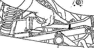
Fig. 30. Checking the chain sag
|
Tensioning the chain |
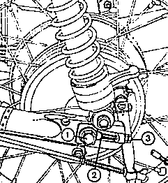
Fig. 31. Tensioning the chain
| (1) | Knockout axle |
| (2) | Chain tensioner, left-hand side |
| (3) | Adjusting nuts |
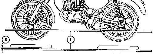
Fig. 32. Aligning the wheels
| (1) | Lath for alignment |
| (S) | Gap between measuring lath and front wheel (about 0.7 cm) |
|
Replacing the chain |
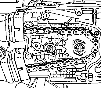
Fig. 33. Mounting position of the end spring of the chain lock
| (1) | End spring |
| (2) | Idling switch |
|
broken pieces of the old chain. You may attach the new chain to the old one and draw it through the chain protection. The locking spring clip of the chain connecting link must be inserted so that the open end is opposite to the sense of rotation. 4.9. Electrical Equipmentnächster Punkt ; IndexTake care to see to it that the insulation of the cables and electrical
devices is always in proper condition and that all line connections are tight and free
from oxide. Never replace blown fuses by other metal objects. |
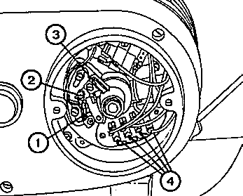
Fig. 34. Three-phase current dynamo and contact breaker
| (1) | Contact breaker |
| (2) | Setting eccentric for contact breaker |
| (3) | Lubricating felt pad for contact breaker |
| (4) | Cable connection for the dynamo |
|
Ignition system |
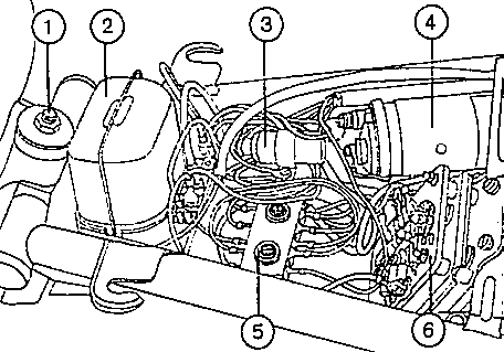
Fig. 35. Electrical equipment under the dual seat
| (1) | Fastening of the fuel tank | (4) | Ignition coil |
| (2) | Regulator of the dynamo | (5) | Line connector at chassis |
| (3) | Interference suppression capacitor | (6) | Rectifier of the dynamo |
|
Battery |
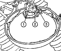
Fig. 36. Replacement of electric bulbs for headlamp
| (1) | Retaining spring |
| (2) | Connecting piece of twin-filament bulb |
| (3) | Cable for parking lamp |
|
Notice! |
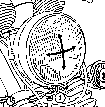
Fig. 37. Mounting of headlamp
| (1) | Fastening screw |
|
Headlamp |
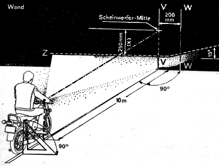
Fig. 38. Focusing and adjustment diagram for headlamp
| Wand | Wall |
| Scheinwerfer-Mitte | Headlamp Centre |
|
The contacts must be clean and put on correctly. Do not touch the glass
bulb of the incandescent lamps with your fingers! 4.10. Information about Winter Operationnächster Punkt ; IndexWe ask all of our customers who will use their vehicles in winter, to
take into consideration the information given below. 5. Faults and Their Remediesnächster Punkt ; Index
6. After-sales Servicenächster Punkt ; IndexIn all of your inquiries, please, give full information both as to your vehicle and as to the defect presumed. As a rule, however, you should call on one of our authorised Workshops. We are not in a position to deliver spare parts directly to you. We only deliver spare parts to our authorised Workshops and MZ special sales shops and to our importers in foreign countries. 7. For Making the Motor-cycles Completenächster Punkt ; IndexFor reasons of facilitating transport, a few parts have not been mounted by the manufacturer. These parts must be mounted subsequently in order to complete the vehicle. When connecting the rear lighting fittings to the line connector, ground point and fuse box, observe the wiring diagram. Correctly attach the flashing-light direction indicators and do not omit the packings between flashing-light direction indicator and its carrier. Remove the foil from under the oil filler screw plug in order that the ventilation of the gearbox compartment becomes free. | ||||||||||||||||||||||||||||||||||||||||||||||||||||||||||||||||||||||||||||||||||||||||||||||||||||||||||||||||||||||||||||||||||||||||||||||||||||||||||||||||||||||||||||||||||||||||||||||||||||||

Fig. 39. Flashing-light direction indicators (on the left rear, on the right front)
| (1) | Edge for checking the flashing procedure |
| (2) | Plastic reflector |
| (3) | Terminals |
| (4) | Packing |
8. Fresh-oil Dosing DeviceIndexIf your ETZ is provided with an oil proportioning device, please, observe the following instructions in addition to the explanations given in the general Operating Instructions.
|
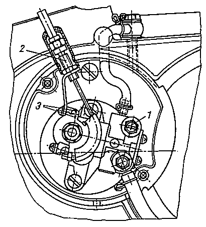
Fig. 40. Maintenance of the dosing pump
| (1) | Bleeder screw |
| (2) | Cable control setting screw |
| (3) | Marking of the setting point |
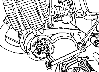
Fig. 41. ETZ 125/150 with oil dosing device