Index
Preface
In the high latitudes of Finland, in the parching heat of Africa, hence,
under the most different conditions, the MZ moto-cycles run to the satisfaction of their
owners.
To ensure that the vehicles remain in perfect working order and reliable in service after
a long period of operation, involving a certain amount of wear, we issue this Repair
Manual to give the necessary instructions to our MZ-Workshops at home and abroad.
Repair work is a matter of confidence in several respects:
The safety of the driver depends an the reliability and workmanship of the mechanic.
The finding of the actual cause of the trouble ensures that no material is wasted and
labour costs are restricted to a minimum.
From these items, 3 advantages result:
- No retouching work,
- short times of inoperation, and
- low repair costs!
A good workmanship in repairs largely depends on the use of the special
tools and means recommended by MZ. We should like to underline that especially self-service
workshops and amateur constructors should bear this in mind in order to avoid considerable
additional expenditure of labour and material costs.
Our MZ-Workshops may purchase the special tools from the MZ Spare Sales Department - for
amateur constructors, there is only the possibility of constructing them with the help of
the sketches given in Section 8.2.
We hope this Reference Book offers the required information to the staffs of the workshops
contracted for servicing our products at home and abroad, and to the friends of MZ
motor-cycles throughout the world; and we wish good success to each and all.
VEB MOTORRADWERK ZSCHOPAU
Betrieb des IFA-Kombinates Zweiradfahrzeuge
Service Department
Table of Contents
| 1. | Technical Data |
| 1.1. | Engine |
| 1.2. | Carburetter |
| 1.3. | Electrical Equipment |
| 1.4. | Gearbox |
| 1.5. | Power Transmission |
| 1.6. | Cycle Parts |
| 1.7. | Masses (Weights) |
| 1.8. | Capacities |
| 1.9. | Dimensions, Measured Values, Diagrams |
| 2. | Fuel, Lubricants and Fluids |
| 2.1. | Fuel |
| 2.2. | Two-stroke Engine Oil for Preparing the Fuel-oil Mixture |
| 2.3. | Lubricants for Motor-cycles Provided with Oil Dosing Equipment |
| 2.4. | Amount of Oil in Gearbox |
| 2.5. | Lubricants for the Cycle Parts |
| 2.6. | Shock-absorber Oil - Telescopic Fork |
| 2.7. | Shock-absorber Oil - Spring-loaded Suspension Units |
| 2.8. | Lubricant for Contact Breaker |
| 2.9. | Brake Fluid |
| 3. | Disassembly of the Engine |
| 3.1. | Preliminaries |
| 3.1.1. | Right-hand Side of Motor-cycle |
| 3.1.2. | Demounting the Carburetter |
| 3.1.3. | Demounting the Engine |
| 3.2. | Dismantling the Engine |
| 3.2.1. | Preliminaries |
| 3.2.2. | Removing the Clutch Cover |
| 3.2.3. | Removing the Clutch and the Primary Drive |
| 3.2.4. | Removing the Kick-starter and the Revolution Counter Drive |
| 3.2.5. | Removal of the Cylinder Assembly |
| 3.2.6. | Engine - Demounting the Dynamo Side |
| 3.2.7. | Separating the Two Casing Halves |
| 3.2.8. | Removing the Gear-shift Mechanism and the Gearbox |
| 3.2.9. | Dismantling the Gear-shift Shaft |
| 3.2.10. | Pressing-out the Crankshaft |
| 3.2.11. | Demounting the Bearings |
| 3.2.12. | Pulling the Bearings from the Crankshaft |
| 3.3. | Cleaning all Engine Parts |
| 3.4. | Inspections for Wear |
| 3.4.1. | Clutch and Clutch Actuation Mechanism |
| 3.4.2. | Primary Drive |
| 3.4.3. | Kick-Starter |
| 3.4.4. | Gears, Shafts and Gear-shift Forks |
| 3.4.5. | Gear-shift Mechanism |
| 3.4.6. | Crank Assembly |
| 3.4.6.1. | Cylinder and Piston |
| 3.4.6.2. | Checking Piston and Cylinder |
| 3.4.6.3. | Elimination of a Slight Piston Jamming |
| 3.4.6.4. | Piston Rings |
| 3.4.6.5. | Cylinder Cover |
| 3.4.6.6. | Crankshaft |
| 3.4.7. | Casing and Packings |
| 3.4.8. | Radial Grooved Ball Bearings for Crankshaftand Gearbox |
| 4. | Assembling the Engine |
| 4.1. | Preliminaries |
| 4.1.1. | Selection of Piston and Cylinder |
| 4.1.2. | Regeneration of the Cylinder |
| 4.1.3. | Selection of the Needle Bearing for the Gudgeon Pin |
| 4.2. | Pre-assembling the Replacement Casing |
| 4.3. | Preparing the Left-hand Casing Half |
| 4.4. | Mounting the Crankshaft and the Gearbox |
| 4.5. | Mounting the Right-hand Casing Half |
| 4.6. | Mounting Piston, Cylinder and Cylinder Cover |
| 4.6.1. | Piston and Cylinder |
| 4.6.2. | Cylinder Cover and Compression Ratio |
| 4.7. | Mounting the Revolution Counter Drive and the Kick-starter |
| 4.8. | Mounting the Primary Drive |
| 4.9. | Mounting the Clutch |
| 4.10. | Mounting the Engine |
| 5. | Cycle Parts |
| 5.1. | Rear Wheel Springing and Elastic Rear Engine Support |
| 5.1.1. | Bearing of the Rear Wheel Swing Arm |
| 5.1.2. | Replacement of the Rubber Bearing - Rear Wheel Swing Arm |
| 5.1.3. | Demounting and Mounting the Swing Bearing Bolt |
| 5.1.4. | Mounting the Rear Swing Including the Engine Suspension |
| 5.1.5. | Rear Engine Suspension |
| 5.1.6. | Repairing the Spring-loaded Suspension Units |
| 5.2. | Engine Suspension at the Cylinder Cover |
| 5.3. | Telescopic Fork |
| 5.3.1. | Steering Bearing |
| 5.3.2. | Criteria for Demounting the Telescopic Fork |
| 5.3.3. | Demouting and Mounting the Complete Telescopic Fork |
| 5.3.4. | Demounting and Mounting the Telescopic Fork Members |
| 5.3.5. | Dismantling the Telescopic Fork Members Removed from the Vehicle |
| 5.3.6. | Mounting the Telescopic Fork Members and Checking for Wear |
| 5.3.7. | Functional Test of the Telescopic Fork |
| 5.4. | Fuel Tank |
| 5.5. | Fuel Shut-off Cock |
| 5.6. | Rear Wheel Drive and Rear Wheel Hub |
| 5.6.1. | Dismantling the Rear Wheel Drive |
| 5.6.2. | Speedometer Drive |
| 5.7. | Replacement of the Wheel Bearing |
| 5.8. | Brakes |
| 5.8.1. | Internal-expanding Shoe Brake |
| 5.8.2. | Disk Brake for the Front Wheel |
| 5.9. | Secondary Chain |
| 5.10. | Aligning the Wheels, Balancing the Front Wheel |
| 5.11. | Exhaust System |
| 5.12. | Cable Controls |
| 6. | Electrical Equipment |
| 6.1. | Three-phase Current Dynamo |
| 6.1.1. | Mode of Operation |
| 6.1.2. | Technical Data |
| 6.1.3. | Technical Characteristic |
| 6.1.4. | Fault Diagnoses |
| 6.1.5. | Behaviour of the Charging Control Lamp |
| 6.1.6. | Measuring Instruments |
| 6.1.7. | Measurements in the Vehicle |
| 6.1.7.1. | Fault Location - Simple Method |
| 6.1.7.2. | Fault Location Scheme |
| 6.1.8. | Removal from the Vehicle |
| 6.1.8.1. | Demounting the Three-phase Current Dynamo |
| 6.1.8.2. | Demounting the Rectifier |
| 6.1.9. | Dismantling the Three-phase Current Dynamo |
| 6.1.9.1. | Stator with Retaining Cap |
| 6.1.9.2. | Rectifier |
| 6.1.10. | Checking the Components |
| 6.1.10.1. | Checking the Rectifier |
| 6.1.10.2. | Checking the Stator |
| 6.1.10.3. | Checking the Rotor |
| 6.1.10.4. | Checking the Length of the Carbon Brushes |
| 6.1.11. | Assembling Instructions |
| 6.1.12. | Important Information |
| 6.2. | Regulator |
| 6.2.1. | Mounting |
| 6.2.2. | Maintenance |
| 6.2.3. | Adjustment |
| 6.2.4. | Damages and Their Causes |
| 6.3. | Battery |
| 6.4. | Ignition |
| 6.4.1. | Ignition Coil |
| 6.4.2. | Contact Breaker |
| 6.4.3. | Spark Setting |
| 6.4.4. | Sparking-plug |
| 6.4.5. | Ignition Line Terminal (Plug Terminal) |
| 6.4.6. | Faults in the Ignition System |
| 6.5. | Lighting and Signalling Installation |
| 6.5.1. | Headlamp |
| 6.5.2. | Combined Stop, Tail, Number-plate Lighting Fitting |
| 6.5.3. | Ignition-light Switch |
| 6.5.4. | Switch Combination at the Handle-Bars |
| 6.5.5. | Stop-light Switch |
| 6.5.6. | Flashing-light Direction Indicator System |
| 6.5.7. | Horn |
| 6.5.8. | Wiring diagram and Circuit Diagram |
| 6.6. | Instruments and Indicator Lamps |
| 7. | Induction System |
| 7.1. | Description and Function of the System |
| 7.1.1. | Air Filter |
| 7.1.2. | Intake Silencer |
| 7.1.3. | Connecting Piece to Carburetter |
| 7.1.4. | Carburetter |
| 7.1.4.1. | Design and Function of the Carburetter |
| 7.1.4.2. | Fuel Level - Basic Setting |
| 7.1.4.3. | Slow-running Adjustment |
| 7.1.5. | Intake Socket |
| 7.2. | Fault Finding Procedure |
| 7.2.1. | Too Lean Mixture |
| 7.2.2. | Too Rich Mixture |
| 7.3. | Oil dosing |
| 8. | Special Tools |
| 8.1. | List of Special Tools |
| 8.2. | Drawings for Special Tools |
|
Fig. 1. ETZ 125/150 with disk brake
Fig. 2. ETZ 125/150 with drum brake in standard design

Fig. 3. Exploded view of the EM 125/150 engine
Fig. 4. Cross-section of the EM 125/150 engine
1. Technical Data
1.1. Engine
zum nächsten Punkt ; Index
| | ETZ 125 | ETZ 150 | ETZ 150 |
|---|
| Engine type | EM 125 | EM 150.2 | EM 150.1 |
| Cycle | two-stroke reverse scavenging |
| Type of cooling | air (relative wind) |
| Number of cylinders | 1 | 1 | 1 |
| Stroke/bore (mm) | 58/52 | 58/56 | 58/56 |
| Swept volume (cm³) | 123 | 143 | 143 |
| Compression ratio | 10 : 1 | 10 : 1 | 10 : 1 |
Compression volume of the cylinder cover
(in the mounted state) (cm³) | 14.25 ± 0.5 | 15.8 ± 0.5 | 15.8 ± 0.5 |
| Maximum output | 7.5 kW (10.2 hp) | 9.0 kW (12.2 hp) | 10.5 kW (14.2 hp) |
| at about | 6,000 rpm | 6,000 rpm | 6,500 rpm |
FRG
| | 7.5 kW (10 hp)
6,000 rpm | |
| Maximum torque | 12.3 Nm (1.2 kpm) | 15 Nm (1.5 kpm) | 15.8 Nm (1.6 kpm) |
| at about | 5,500 rpm | 5,400 rpm | 6,200 rpm |
FRG
| | 13 Nm (1.3 kpm)
5,000 rpm | |
| Lubrication | petroil lubrication or, for selected export countries, oil feed through oil dosing equipment |
| Connecting-rod bearings | cage-type needle bearings for big end and gudgeon pin
1 bearing 6304 TNG 4 f, TGL 2981 (20x52x15)
2 bearings 6204 TNWC 4 f, TGL 2981 (20x47x14)
matched |
| Lubrication of the main bearings | petroil lubrication |
| Timing in terms of crank angle |
| induction | 151 | 151 | 155 |
| transfer | 114 | 114 | 120 |
| exhaust | 165.5 | 169.5 | 179 |
1.2. Carburetter
zum nächsten Punkt ; Index
| | ETZ 125 | ETZ 150 | ETZ 150 |
|---|
| Carburetter type | BVF 22 N 2-2 | BVF 24 N 2-2 | BVF 24 N 2-2 |
| Induction Port | 22 mm | 24 mm | 24 mm |
| Main jet | 100 | 120 | 120 |
| Needle jet | 70 | 70 | 70 |
| Air-correction jet (drilled into needle jet) | 2x60 | 2x60 | 2x60 |
| Partial-load needle | 2.5 A 513 | 2.5 A 513 | 2.5 A 513 |
| Needle position from top | 3¹) | 3¹) | 3¹) |
| Starting jet | 70 | 70 | 70 |
| Slow-running jet | 50 | 40 | 40 |
| Float-needle valve | 15 | 15 | 15 |
| Slow-running air screw (revolutions open) | about 1.5; but adjustment of the maximum concentration of CO in exhaust gas to 2.5 to 3.5 with percentage by volume at 1,200 rpm |
| Throttle valve opening | 30 | 40 | 40 |
| ¹) 2 after running-in |
1.3. Electrical Equipment
zum nächsten Punkt ; Index
| | ETZ 125 | ETZ 150 | ETZ 150 |
|---|
| Ignition | battery ignition |
| Ignition timing | 2.5+0.5 mm before T.D.C. = 22°45' to 23°45' |
| Contact breaker points gap | 0.3+0.1 mm |
| Sparking-plug | ZM 14-260 |
| Electrode gap | 0.6 mm |
| Dynamo | 14 V, 15 A, three-phase current |
| Rectifier | silicon semi-conductor in 3-phase bridge circuit |
| Regulator | one-system regulator, temperature-compensated, positively regulating |
| Battery | 12 V, 5.5 Ah |
| Ignition coil | 12 V small ignition coil |
| Headlamp | light emitting opening 170 mm in diameter
(optionally H 4), symmetric passing beam |
| Combined stop, tail and number-plate lighting fitting | light emitting opening 122 mm in diameter |
| Horn | under the fuel tank |
| Direction indicator | 4-lamp flashing-light System |
| Switches |
| Ignition light switch | in instrument holder |
| Switch-combination at the handle-bars | dimmer switch
flashing-light direction indicator, horn,
light switch
by-pass light signal |
| Stop light switch | in rear-wheel hub and hand brake lever (drum brake)
or brake master cylinder |
| Electric bulbs |
| Headlamp | 12 V 45/40 W (twin-filament bulb) or TGL 11413
12 V 60/55 W (H 4) TGL 200-8188 |
| Parking light | 12 V 4 W cap BA 9 s TGL 10833 |
| Stop light | 12 V 21 W cap BA 15 s TGL 10833 |
| Direction indicator | 12 V 21 W cap BA 15 s TGL 10833 |
| Tail light | 12 V 5 W cap BA 15 s TGL 10833 |
| Charging control light | 12 V 2 W cap BA 7 sTGL 10833 |
| Idling indicating light | 12 V 2 W cap BA 7 s TGL 10833 |
| High-beam headlight indicator | 12 V 2 W cap BA 7 s TGL 10833 |
| Control of direction indicator | 12 V 2 W cap BA 7 s TGL 10833 |
| Speedometer illumination | 12 V 2 W cap BA 7 s TGL 10833 |
| Fuses |
| Main fuse (2 fuses) | fuse link 16 A (A 16, TGL 11135) |
| Direction indicator | fuse link 4 A (A 4, TGL 11135) |
| Dynamo (line DF) | fuse link T 2 A (micro-fuse 2 A) |
1.4. Gearbox
zum nächsten Punkt ; Index
| | ETZ 125 | ETZ 150 | ETZ 150 |
|---|
| Clutch | multi-plate clutch in oil bath with Belleville spring |
| Gear-shift system | foot-operated |
| Number of speeds | 5 | 5 | 5 |
| Gear ratios |
| 1st speed | 3.833 = 12 : 34 and 17 : 23 teeth |
| 2nd speed | 2.345 = 15 : 26 and 17 : 23 teeth |
| 3rd speed | 1.567 = 19 : 22 and 17 : 23 teeth |
| 4th speed | 1.191 = 25 : 22 and 17 : 23 teeth |
| 5th speed | 1 direct |
| Revolution counter drive | 4 = 16 : 4 |
| Speedometer drive | 1.75 = 21 : 12 |
1.5. Power Transmission
zum nächsten Punkt ; Index
| | ETZ 125 | ETZ 150 | ETZ 150 |
|---|
| Transmission |
| engine - gear | 2.055 = 18 : 37 teeth |
| by double-strand silent chain | 3/8" x 3/16" 06 C 2 acc. to ISO, 50 links, endless |
| Transmission |
| gear - rear wheel | 3.2 = 15 : 48 teeth | 3.0 = 16 : 48 teeth | 3.2 = 15 : 48 teeth |
| by roller chain | 0.8 B-1-128 TGL 11796/03 (128 rollers) (12.7 x 7.75 x 128) |
| Total gear ratio |
| 1st speed | 25.215 | 23.639 | 25.215 |
| 2nd speed | 15.426 | 14.461 | 15.426 |
| 3rd speed | 10.305 | 9.660 | 10.305 |
| 4th speed | 7.831 | 7.342 | 7.831 |
| 5th speed | 6.578 | 6.167 | 6.578 |
| Kick-starter total ratio | 3.197 = 18 : 37 and 27 : 42 |
1.6. Cycle Parts
zum nächsten Punkt ; Index
| | ETZ 125 | ETZ 150 | ETZ 150 |
|---|
| Frame | central tubular frame (welded rectangular section) |
| Engine suspension (elastic) | at cylinder cover and at the casing rear |
| Steering angle | 63° |
| Caster | 105 mm |
| Type of springing |
| front | telescopic fork with oil-hydraulic damping spring deflection 185 mm |
| rear | spring-loaded suspension units with oil-hydraulic damping, spring pre-load adjustable, spring deflection 105 mm; two hinged fastening points for spring loaded suspension units at rear swing arm |
| Wheels | wire-spoke wheels with non-offset spokes |
| Rim size |
| front | 1.60 x 18 |
| rear | 1.85 B x 16 |
| Tyres |
| front | 2.75 - 18 |
| rear | 3.25 - 16 |
| Tyre inflation pressure |
| Solo: front | 150 kPa (1.5 kp/cm²) |
| rear | 190 kPa (1.9 kp/cm²) |
| With permissible total mass: |
| front | 150 kPa (1.5 kp/cm²) |
| rear | 270 kPa (2.7 kp/cm²) |
| Brakes |
| front | drum brake,
diameter 150 mm
lining width 30 mm
actuation by cable control
or
hydraulic single-plate fixed saddle brake,
brake disk diameter 280 mm |
| rear | drum brake,
diameter 150 mm
lining width 30 mm
actuation by linkage |
1.7. Masses (Weights)
zum nächsten Punkt ; Index
| | ETZ 125 | ETZ 150 | ETZ 150 |
|---|
| Weight unladen (with fuel and tools) | 118 to 122 kg (depending an design) |
| Permissible total weight | 290 kg | 290 kg | 290 kg |
1.8. Capacities
zum nächsten Punkt ; Index
| | ETZ 125 | ETZ 150 | ETZ 150 |
|---|
| Gearbox | 500 cm³ | 500 cm³ | 500 cm³ |
| Fuel tank | 13.0 l ¹ | 13.0 l ¹ | 13.0 l ¹ |
| Oil container for oil dosing system | 1.3 l | 1.3 l | 1.3 l |
| Telescopic fork | 230 cm³ | 230 cm³ | 230 cm³ |
| ¹) including about 1.5 l of reserve |
1.9. Dimensions, Measured Values, Diagrams
zum nächsten Punkt ; Index
| | ETZ 125 | ETZ 150 | ETZ 150 |
|---|
| Maximum Speed | 100 km/h | 105 km/h | 110 km/h |
| Acceleration from 0 to 80 km/h | 12.5 s | 11.3 s | 11.0 s |
| Fuel consumption l/100 km | 3.5 | 3.5 | 4.0 |
|
Fig. 5a. Full-load characteristics of the engine EM 125 and of the engine EM 150, 9 kW (12.2 hp) (dashed, curve of torque extends to right Md-scale)
Fig. 5b. Full-load characteristics of the engine EM 150, 10.5 kW (14.2 hp)
Fig. 6a. Rotational speed/gear diagram of ETZ 125/ETZ 150 10.5 kW
| Motordrehzahl in U/min | Engine speed in rpm |
| Geschwindigkeit v in km/h | Speed in km/h |
Fig. 6b. Rotational speed/gear diagram of ETZ 150 9 kW
| Motordrehzahl in U/min | Engine speed in rpm |
| Geschwindigkeit v in km/h | Speed in km/h |
2. Fuel, Lubricants and Fluids
2.1. Fuel
zum nächsten Punkt ; Index
According to the design of the engine, a petrol of an octane rating of at
least 88 (abbreviated as ROZ 88 - called "normal" fuel in the GDR) should be
used.
In countries other than the GDR, the use of a fuel with a similar rating is
recommended.
2.2. Two-stroke Engine Oil for Preparing the Fuel-oil Mixture
zum nächsten Punkt ; Index
The engine oil for two-stroke engines is added to petrol in the
ratio of 1 : 50
(e.g. 0.2 litres of two-stroke engine oil to 10 l of fuel).
This mixing ratio of 1 : 50 also applies to the running-in period.
This simple and reliable system of petroil lubrication supplies oil to the two
connecting-rod bearings, cylinder liner, piston and the crankshaft main bearings.
Experiences gathered by us in the course of many years have shown that it is advisable to,
use exclusively
MZ22 two-stroke engine oil
in the GDR.
This additive-type oil meets the following technical requirements:
viscosity at 50 °C is between 20 and 25 mm²/s
(20 to 25 cSt) pour point maximum -30 °C
For MZ motor-cycles operated in countries other than the GDR, we
also recommend the exclusive use of two-stroke engine oils which possess these properties
(e.g. Shell 2 T, Castrol 2 T, Aral 2 T, Mixol "S", LT-2 T, etc.).
2.3. Lubricants for Motor-cycles Provided, with Oil Dosing Equipment
zum nächsten Punkt ; Index
For engine lubrication; fill the container for oil with a branded
two-stroke oil (e.g. Castrol 2 T, Shell 2 T, etc.) or a lubricating oil for four-stroke
engines of a similar viscosity and quality.
2.4. Amount of Oil in Gearbox
zum nächsten Punkt ; Index
For the gearbox and the primary drive, 500 cm³ of gear oil
"GL 100" are required.
This is an additive-type gear oil which is suitable for the lubrication of change-speed
gearbox and axle drive. It is an ageing-resistant refined lubricating oil with additives
for an increase of load-bearing capacity and a reduction of wear.
It has favourable low-temperature properties and meets the following technical
requirements:
| viscosity at 40 °C | to 110 mm²/s (110 cSt) |
| pour point maximum. | -25 °C |
| flashpoint | 180 °C |
| water content | 0.1% |
In countries other than the GDR engine oil SAE 30 to 40 or gear oil
SAE 80 with the same properties should be used.
2.5. Lubricants for the Cycle Parts
zum nächsten Punkt ; Index
The following lubricating points of the cycle parts must be lubricated
with antifriction bearing grease "SWA 532" TGL 14819:
Steering bearing, wheel bearings, bearing for rear-wheel drive, secondary chain, brake
cams and brake shoes bearings, foot-operated brake shaft, and speedometer drive (the two
latter parts only when being mounted or repaired).
This antifriction bearing grease has a pour point of about 130 to 150°C, can be used for
a temperature range from -20 to +100°C, and it is water-resistant up to +50°C.
In countries other than the GDR, an antifriction bearing grease of similar
characteristics should be used.
2.6. Shock-absorber Oil - Telescopic Fork
zum nächsten Punkt ; Index
As a damping fluid, a mixture of
50% of shock-absorber oil and
50% of two-stroke engine oil
should be used.
Shock-absorber oil viscosity:
8 to 12 mm²/s (8 to 12 cSt) at 50 °C.
2.7. Shock-absorber Oil - Spring-loaded Suspension Units
zum nächsten Punkt ; Index
Shock-absorber oil without additives and the above-mentioned
viscosity only has to be used.
The damping characteristics of the telescopic fork and the spring-loaded suspension units
are based an this viscosity. Damping and roadability will be impaired if shock-absorber oil
of a different viscosity will be used.
2.8. Lubricant for Contact Breaker
zum nächsten Punkt ; Index
Special oil for ignition contact breakers, viscosity 700 to 1,300 mm²/s
(700 to 1,300 cSt) at 50°C.
2.9. Brake Fluid
zum nächsten Punkt ; Index
For the disk brake, brake fluid "Karipol grün" or, in
foreign countries, a brake fluid SAE 70 R3 or SAE J 1703 (for disk brakes) should be
used.
3. Disassembly of the Engine
3.1. Preliminaries
zum nächsten Punkt ; Index
It is advisable, before starting the disassembling operations, to disconnect
the battery and to remove it from the vehicle. During the repair period, it can be serviced
and re-charged. When the motor-cycle is kept in the workshop, the two fuses should be
removed from the fuse holder under the right-hand panel.
During the subsequent operations, the gear oil should be allowed to drain [open the oil
drain plugs (1) and (2)].
NOTICE! The neutral detent screw (3) does not serve for oil draining!
|
Fig. 7. Draining the oil from gearbox and clutch compartment
3.1.1. Right-hand Side of Motor-cycle
zum nächsten Punkt ; Index
At the right-hand side, the operations are started with disassembling the
exhaust system:
- Union nut at the cylinder to be loosened by means of hook spanner,
- Exhaust pipe holder at the front of the engine (width across flats 17),
- Rear brace at the silencer (spanner width across flats 13), and
- Dynamo cover to be removed (hexagonal socket head width across flats 5) and clutch
cable control (1 in Fig. 9) to be unhooked. For this purpose, draw
the cable control sheath out of the cover in the direction of the arrow-head, turn
the cable control and lift it out of the lever.
|
Fig. 8. Right-hand side of motor-cycle
Fig. 9. Unhooking the clutch cable control (1)
After having withdrawn the cables (1), unscrew the brush holder (2). The
stator can be removed after loosening the fastening screws (3). A box spanner (width across
flats 13) serves for loosening the fastening screw of the cam of the dynamo. Sense of
rotation of the spanner is opposite to the sense of rotation of the engine. The cam can
then be pulled off when slightly shaking the fastening screw (thread M 7).
|
Fig. 10. Demounting the stator of the dynamo
Fig. 11. Pressing off the rotor of the dynamo
The pressing-off screw 02-MW 39-4 (1) disconnects
the rotor from the cone of the crankshaft (apply a bouncing blow with the hand an the lock
in the sense of rotation of the engine).
For the amateur constructor or home-mechanic, a M 10x100 hexagon-head screw will do good
service.
The chain need not be opened when the sprocket is removed together with the chain from
the shank wheel (see also Fig. 13).
3.1.2. Demounting the Carburetter
zum nächsten Punkt ; Index
The carburetter is to be removed only after having closed the fuel shut-off
cock and withdrawn the fuel hose.
Sequence of operations for removing the carburetter from the motor-cycle:
- Raise the protective rubber cap and unscrew the starting carburetter actuation
arranged under this cap (spanner width across flats 14)
- Unscrew the carburetter casing cap and draw it out together with the throttle valve
- Loosen the clamping connection between carburetter and induction pipe (use a
screw-driver)
- Loosen the clamping screw (spanner width over flats 10) of the induction socket
fastening
|
Fig. 12. Demounting the carburetter
Pull the carburetter from the induction socket at the cylinder, turn it to
the left and draw it out of the induction pipe (rubber).
Then unscrew the flexible shaft for the revolution-counter drive (5).
3.1.3. Demounting the Engine
zum nächsten Punkt ; Index
Demounting the engine:
- Remove two nuts (width across flats 13) (1) together with corrugated washers from
the stay bolt of the cylinder cover. Prop the engine from below.
- Unscrew two fastening screws (2) for the engine from the rear of the engine shoes
(width across flats 13, socket wrench).
- The engine tilted over downwards is then pulled out of the vehicle forward.
Replacement of the cylinder:
The cylinder cover, the cylinder and the elastie engine suspension can also be replaced
in the assembling position shown in Fig. 13.
If necessary, loosen the rear upper engine fastening screw in addition to the engine
mounting at the cylinder. The dynamo may be left at the engine.
|
Fig. 13. Demounting the engine or replacing the cylinder
3.2. Dismantling the Engine
3.2.1. Preliminaries
zum nächsten Punkt ; Index
Before disassembling the engine removed from the motor-cycle into its
parts, we think you agree that the engine should be cleaned externally. It also goes
without saying that all parts should be placed or kept in such a way that nothing can
be lost or damaged.
3.2.2. Removing the Clutch Cover
zum nächsten Punkt ; Index
After loosening the clamping bolt with nut (width across flats 10), remove
the gear-change pedal (1). After loosening the clamping screw (width across flats 13), the
kick-starter crank (2) is pulled off.
In vehicles with oil dosing equipment, then remove the cover of this equipment and demount
the dosing pump.
|
Fig. 14. Removing the clutch cover
After removing the 5 fastening screws of the cIutch cover, disconnect the
clutch cover by applying blows with a plastic or rubber mallet at the front and rear end
of the cover.
3.2.3. Removing the Clutch and the Primary Drive
zum nächsten Punkt ; Index
At first bend up the locking plates (1) and then remove the three screws
(2) by means of a spanner having a width across flats of 10 mm. Then remove the complete
disk parcel out of the clutch drum.
|
Fig. 15. Demounting the clutch
After applying the holding-up device (1) and the clamping piece (2),
unlock the nut on the clutch shaft and loosen it (left-hand thread, width across flats
19). Remove the clutch driver.
The fastening screw of the sprocket wheel, width across flats 19, has a right-handed
thread.
|
Fig. 16. Removing the clutch driver
Fig. 17. Pulling the sprocket pinion
Then using the puIler 12 MV 32-4, disconnect the
sprocket pinion from the crankshaft. The puller must be tightly screwed to the sprocket.
During the pulling action, the clamping piece remains between the two sprocket wheels.
After having removed the pinion from the cone, unscrew the puller, remove the clamping
piece and remove the two sprocket wheels together with the chain.
3.2.4. Removing the Kick-starter and the Revolution Counter Drive
zum nächsten Punkt ; Index
Slightly turn the kick-starter shaft in order that the segment no longer
contacts the stop, and then draw out the kick-starter shaft with segment and spring.
For dismantling the engine, it is advisable to unscrew the sealing cap (1) at the left-hand
side. The intermediate gear (2) is retained by a lock ring 9 TGL 0-471. This gear must be
pulled off prior to the aforesaid operation. A precision washer 9x0.5 TGL 10404-St is
placed between the lock ring and the wheel. The intermediate shaft (3) may remain in the
casing when the engine is dismantled. If it has to be removed for other reasons, then -
after unlocking and screwing out the hexagonhead screw (4) (width across flats 8) - it must
be drawn out of the casing together with the bearing bush. Finally, unhook the neutral
detent screw (5) and take it off from the notched pin.
|
Fig. 18. Demounting the revolution counter drive
3.2.5. Removal of the Cylinder Assembly
zum nächsten Punkt ; Index
Loosen the nuts (width across fiats 13) one after the other and crosswise
from the cylinder studs by means of a socket wrench, then take off the cylinder cover and
the cylinder.
NOTICE!
When the engine is not to be dismantled, then the opening of the crankcase must be
covered with a clean rag!
Press out the gudgeon pin by means of the pressing-out device (1)
22-50.010 and take off the piston from the connecting rod.
NOTICE!
Beating out the gudgeon pin is detrimental to the crankshaft and destroys the needle
bearing an the gudgeon pin!
|
Fig. 19. Pressing out the gudgeon pin
3.2.6. Engine - Demounting the Dynamo Side
zum nächsten Punkt ; Index
- Unscrew idle gear contact switch (3).
- Before loosening the nut of the sprocket wheel (width across flats 27, right-hand
thread!) bend up the lock plate (1) and apply the holding-up device (2) with chain
- clutch thrust pin is drawn out.
- Pull the sprocket wheel from the gear and unscrew the sealing cap (4) under it.
|
Fig. 20. Removing the sprocket wheel from the gearbox
- Unscrew the sealing cap for the crankshaft bearing (5), take it off together with the
packing and remove the compensating shims.
- Remove the plate spring 4x5 TGL 9499 for the armature detent an the crankshaft.
- Loosen the casing fastening screws (11 screws) by means of a screw-driver and take
them out of the casing.
- Open the tommy screw of the engine assembling device.
3.2.7. Separating the Two Casing Halves
zum nächsten Punkt ; Index
The assembly bridge 22-50.430 is screwed to the
right-hand casing half by means of two screws M 5 (1) and one screw M 6 (2). Then turn out
the neutral detent screw (No. 3 in Fig. 7).
The two casing halves are separated by means of the clutch puller (3) by uniformly turning
the thrust spindle and slight blows by means of a rubber mallet against the members
receiving the chain protection hoses (4).
NOTICE!
The use of other aids such as a screw-driver, chisel and the like leads to the
destruction of the casing!
Take off the right-hand casing half and clamp the left-hand casing half in
the engine assembly device.
|
Fig. 21. Separating the casing
Fig. 22. Demounting the gearbox
- Draw out the guide pin (3) for the gear-shift fork.
- Alternately remove the gear-shift wheels together with the gear-shift forks from the
countershaft and clutch shaft.
For this purpose, turn the gear-shift forks laterally out of the control roller (4).
- Drive out the clutch shaft and countershaft from the clutch side.
NOTICE!
Use an aluminium mandrel in order to protect the ends of the shaft.
- Draw control roller (4) and gear-shift shaft (5) together out of the casing.
- Take the separating disk (6) of rubber out of the oil catch pocket of the casing.
3.2.9. Dismantling the Gear-shift Shaft
zum nächsten Punkt ; Index
The arresting lever (1) can be drawn out of the gear-shift shaft (2)
without any difficulty. For removing the return spring (4) and the control finger (7),
the lock washers (3) and (5) must be pressed out of their grooves by means of a
screw-driver, and the washer (4a) must be removed.
|
Fig. 23. Arrangement of the gear-shift mechanism
- Locking lever
- Gear-shifting shaft with control member
- Lock washer 9 TGL 0-6799
- Return spring for gear-shifting shaft
a) Washer ø 20 x ø 12.6 x 0.9
- Lock washers 7 TGL 0-6799
- Torsion spring for gear-shift finger
- Gear-shift finger
- Gear-shift roll
- Insulating disk for idle-gear indicating switch
- Contact for idle-gear indication (countersunk notched nail 3x5 according to TGL 0-1477-4.6)
- Gear-shift fork 011 for 1st and 2nd speed
- Gear-shift fork 013 for 3rd speed
- Gear-shift fork 015 for 4th and 5th speed
- Guide pin for gear-shift forks
Fig. 24. Pressing-out the crankshaft
- Press out the crankshaft by means of the pressure spindle (4) of the pulling sleeve by
turning clockwise; at the same time, your right free hand retains the crankshaft from
below to take care that the shaft will not fall down after leaving the bearing seat.
3.2.11. Demounting the Bearings
zum nächsten Punkt ; Index
Before removing the ball bearings, the two casing halves should be heated
in order that damage to the bearing seats is avoided.
The ball bearings are driven out by means of the driving mandrel
11 MW 7-4 or other suitable mandrels.
Left-hand casing half
Remove the circlips of the bearings 6201 and 6202 at the clutch side and drive out the
bearings from the gear compartment.
The bearings 6204 of the crankshaft mounting have to be driven out from the outside at
the left-hand side in the direction of the crankshaft compartment (the sealing cap has
already been removed after the demounting of the primary drive).
Right-hand casing half
The crankshaft bearing 6304 at the dynamo side can be driven out by means of the driving
mandrel 12 MW 31-4 and the shank wheel bearing 6204 by means of the
driving mandrel 11 MW 7-4 in the direction of the interior of the
casing.
The bearing bush for the needle bearing of the countershaft is pushed out of the right-hand
casing half, which has been heated to a temperature of at least 100 °C, by striking it
against a plane support, e.g. a clean hardwood plate, or the like.
3.2.12. Pulling the Bearings from the Crankshaft
zum nächsten Punkt ; Index
When the crankshaft main bearings have remained an the crankpin during the
demounting operation, then have to be pressed off from the crankshaft by means of the ball
bearing extractor 22-50.431 (1). For this purpose, the two halves
of the tool are applied to the crankshaft between bearing and crank gear, compressed in a
vice and pre-stressed by means of two screws M 8x100 (2).
By screwing in 2 more screws with hardened pin at the beginning of the thread (3), the
bearings are pressed against the crank gears of the crankshaft.
For the bearing 6204 (left-hand side) insert the intermediate ring (4) having the order No.
22-50.432 and for the bearing 6304 (right-hand side) insert the ring 22-50.434.
|
Fig. 25. Pulling the ball bearings from the crankshaft
3.3. Cleaning all Engine Parts
zum nächsten Punkt ; Index
Before the engine parts are subjected to careful inspections for wear,
they must be thoroughly cleaned. The type of equipment and the methods to be used largely
depend on the given facilities.
It should be borne in mind, however, that all parts must be properly clean and not corroded
before they are subjected to further treatment.
Take care to see to it that the passage of the oil ducts for the crankshaft main bearings
in the two casing halves are free. To be sure push a wire through the oil ducts (1).
In the cylinder, clean carbonised spots an the exhaust port and the transfer ports, if
necessary. Remove car-
|
Fig. 26. Checking the oil ducts in the casing
- Oil duct
- Disk
bonaceous deposits from the combustion chamber in the cylinder cover and
the piston head by means of scraper and wire brush. These two surfaces must not show any
tooling marks after cleaning and they must be metallically bright.
About cleaning the piston ring grooves of the piston, information is given in Section
3.4.6.4.
3.4. Inspections for Wear
3.4.1. Clutch and Clutch Actuation Mechanism
zum nächsten Punkt ; Index
Parts particularly subjected to wear:
- EXTERNAL DISK (FRICTION DISK)
Wear will appear to a higher degree when the clutch is improperly adjusted (no free
play of clutch or clutch was allowed to slip for prolonged periods of time).
In the extreme case, the material will be burnt.
When the clutch cannot be re-adjusted any more and when it slips upon acceleration of
the engine, new disks have to be fitted.
New disks have a thickness of 3.4 ± 0.1 mm.
Permissible amount of wear: -0.2 min.
- INTERNAL DISK
Such disks must be replaced when they had become too hot due to clutch slipping or
when they are distorted.
Take care that the disks are annealed normally in production, that is to say, they
must be bright in new condition.
| Thickness in a new condition: | 1.5 | + 0.06 | mm. | | - 0.1 |
Deviation from the plane of the surface is maximum 0.2 mm related to a diameter of
75 mm.
- BELLEVILLE SPRING
The spring action may diminish, that is to say, the travel of the spring is reduced.
In severe cases, the clutch will slip even if all other components are in perfect
working order and the adjustment is correct.
Since proof of the diminished spring action can only be furnished by measurements of
force/spring deflection, measurements which cannot be made in a workshop without any
difficulty, remedy should be made by new alignment and/or a new spring.
- CLUTCH DRUM, KICK-STARTER GEAR
Subject the complete clutch drum to the following checks:
- check if the drivers of the friction-lining disks have produced marks in the
clutch drum.
Small depressions are removed by means of a finishing file. If there are deeper
marks, the part must be replaced by a new one because in this state, the clutch
will fail to separate properly.
- check if the edges of the windows in the driver and the claws of the kick-starter
gear show abnormal wear (these edges are rounded). In case of particularly high
degree of wear, replace the parts in question by new ones otherwise the
kick-starter will slip.
|
Fig. 27. Wear at the clutch drum
- INTERNAL DRIVER
At the internal driver check that the internal toothing meshes with the profile of the
clutch shaft still "free of chatter".
Depressions which just can be seen in the grooved profile of the driver and which are
produced by the clutch (steel) disks are negligible.
In case of depressions of more than 0.1 mm, the internal driver must be replaced by
a new one.
|
Fig. 28. Internal clutch driver
3.4.2. Primary Drive
zum nächsten Punkt ; Index
Subject the sprocket wheel an the crankshaft, the silent chain and the
clutch sprocket wheel to an inspection for wear. For this purpose, provisionally put
this parts in place.
With the engine standing vertically, and when one strand of the chain is taut, the other
one must not show a sag of more than 8 to 10 mm. If the sag of the chain is too large
the chain will "whip", rise an the teeth and break eventually.
|
Fig. 29. Checking the primary drive
3.4.3. Kick-starter
zum nächsten Punkt ; Index
Check the teeth running up the kick-starter segment for wear.
The kick-starter segment must be seated an the kick-starter shaft free from any play. The
ends of the kick-starter spring must not show any crack. Observe the instructions given
for Fig. 27!
3.4.4. Gears, Shafts and Gear-shift Forks
zum nächsten Punkt ; Index
The relief cuts in the claws at the gear-shift wheels (on both sides) and
in the counter-gears are arranged at an angle of a=3°.
In the engaged state (a speed is in engagement), the wedge action of the relief cuts
produce a force having the task of retaining gear-shift wheel and gear (loose gear) in
the meshed condition.
This shows that not only the locking lever (Fig. 23) keeps the individual
speeds in the meshed condition but also the wedge action of the relief cuts contributes to
the same effect.
When the claws of the gear-shift wheels are worn to a high degree, the bearing surface
becomes smaller and the speeds in engagement will jump out of this state.
The gear-shift forks have to be checked for their angular state; they must be exactly at
a right angle to the guide bolts of the gear-shift forks (90°). Slightly distorted
gear-shift forks can be carefully realigned in a cold state.
A gear-shift fork which does not form a right angle with the aforesaid bolt will
continuosly strike against the gear-shift wheel and will become blue in colour in the
same way as the gear-shift wheel. With this, the case-hardening effect will be lost and
the two parts become useless after a short period of operation, they must be replaced by
new ones.
|
Fig. 30. Gear-shift claws and guide grooves
- Wedge angle of 3°
-
| Width of guide groove 3.5 (3.2 from August 1986) | +0.18 | mm |
| +0.10 |
Fig. 31. Gear-shift fork and guide pin
-
| Width of gear-shift fork 3.5 (3.2 from August 1986) | -0.030 | mm |
| -0.078 |
For a proper control of the gear set it is necessary to clean all
individual parts carefully in order that parts that have become blue in colour can be
indentified.
Check the clutch shaft for clean oil holes.
Gears, shafts and gear-shift forks that have become blue in colour must be replaced in
any case. This also applies to the following conditions: when the lock-ring grooves of
the gearbox shafts are heavily worn, when the splines of the shafts and gear-shift wheels
are excessively worn, and when the width (b) of the guidering grooves of the gear-shift
wheels and the width (b) of the gear-shift forks are subjected to excessive wear (Fig.
30 and 31).
Gearbox shafts must not show a radial runout of more than 0.05 mm.
Further, with respect to the gears for the 1st speed, the 2nd speed and with respect to
the shank wheel, take care to see to it that the control edges are in a good condition and
that the gear-shift windows do not show wear marks. The bearing bush in the shank wheel
must not exhibit abnormal wear.
3.4.5. Gear-shift Mechanism (Fig. 23)
zum nächsten Punkt ; Index
Gear-shift roll (8)
The gear-shift roll is scarcely subjected to wear. It is of particular importance that
the driving pins are tightly seated in their holes. This also applies to the contact (10).
On no account should the countersunk notched nail be driven in too far otherwise the
insulating disk will be destroyed.
Gear-shifting shaft (2)
The serration for fastening the foot-operated gear-shift lever will be exposed to unusual
wear when the clamping screw is not tightened properly. The lock washers (3) must be
firmly seated in their grooves. This also applies to the lock washers (5) on the gear-shift
finger.
At the gear-shift finger (7) and the arresting lever (1), pay particular attention to wear
the effective edges. "Round" edges lead to faults in gear-shifting. The welded
connection between bolt and plate of the gear-shift finger must be checked for their
condition. The gear-shift finger must not show excessive clearance in the hole of the
gear-shift member of the gear-shifting shaft.
Defective parts must be replaced by new ones.
3.4.6. Crank Assembly
3.4.6.1. Piston and Cylinder
zum nächsten Punkt ; Index
When the performance of the engine should diminish and this fact cannot be
traced back to wrong ignition timing, carburetter tuning, leaky shaft seal rings or
clogged exhaust system (dynamic pressure too high), and when the demounted piston is
"black" on the entire piston skirt below the piston-ring portion, then piston
and cylinder must be replaced because the pressure of compression and combustion blows
through along the sliding area of the piston rings and the cylinder wall.
In this case, the cylinder shows in the liner (port zone) a pronounced state of wear
(bulging) and below the upper edge of the liner a distinct collar.
The replacement of the worn piston rings alone will not produce the desired effect.
3.4.6.2. Checking Piston and Cylinder
zum nächsten Punkt ; Index
In the new condition of piston and cylinder, the assembly clearance between
cylinder liner and piston is 0.03 mm.
The limit of allowable wear is about 0.1 mm. When this has been reached, a new or a
replacement cylinder must be fitted since the noise increases with increasing assembly
clearance (especially when gases are exchanged and when the engine is unloaded).
The nominal dimension of the piston is measured about 12 mm above the piston lower edge.
Only a new piston, when subjected to a control measurement, can show the stamped on nominal
dimension, taking the measuring specifications into consideration. A piston that has been
operated already will be deformed.
The cylinder must be measured by means of an internal measuring device in the upper and
lower third of the liner. Without the help of a measuring instrument, the wear can be
found by the fact that there is an edge (shoulder) about 7 mm below the upper edge of the
cylinder liner.
3.4.6.3. Elimination of a Slight Piston Jamming
zum nächsten Punkt ; Index
When jamming or sticking of the piston has happened, then - in a slight
case - the piston can be restored to proper working condition by re-finishing the areas
of jamming by means of a corundum stone dipped into a fuel-oil mixture.
Slight points of jamming in the cylinder due to pressed on aluminium remains (caused by
the cylinder) have to be removed by means of fine abrasive paper (grain size about 400),
whereby painstaking care should be observed.
Perform the re-finishing operations on the areas of jamming on piston and cylinder only
in longitudinal direction.
NOTICE!
After the sticking of a piston, it is of no use to remove the areas of sticking and to
restore the piston to proper working condition only while the cause leading to jamming
is not found and not removed.
Below, a few examples of possible causes are given:
- Lack of oil (no fuel-oil mixture but only fuel was filled into the tank in refuelling
or the oil container of the oil dosing device has been empty).
- Lack of fuel and, hence, also lack of oil due to insufficient feed from the fuel tank
to the carburetter. Vent hole in the tank cover clogged.
- Fuel filter cock clogged or the retaining screw in the locking handle excessively
tightened (the locking handle must be free to be moved easily).
- Basic carburetter tuning changed although this is not allowed.
- Ignition timing wrong, consequently, the engine is overheated.
- Exhaust system changed by intervention by an unauthorised person, dynamic pressure
wrong.
- Air filter system defective.
- Engine draws in wrong amount of air (mixture becomes lean in the upper speed range).
3.4.6.4. Piston Rings
zum nächsten Punkt ; Index
Before re-using used pistons, particular attention should be paid to the
piston rings and the ring grooves.
Piston rings sticking due to an excessive supply of, or unsuitable, oil in the fuel
(two-stroke mixture) are carefully removed from the piston. Take care that the rings are
not over-stressed, therefore, use a pair of piston ring pliers or three thin strips of
sheet metal as an aid (Fig. 32).
|
Fig. 32. Taking off the piston rings
The carbon deposits an the internal diameter of the piston ring is removed
and the ring grooves in the piston are carefully cleaned with the help of an old broken
ring of the same type.
|
Fig. 33. Cleaning the piston ring grooves
After this operation, the piston ring must be free to move easily in the
piston ring grooves.
Piston rings must not be exchanged, that is to say, they must be fitted into the same
ring groove from which they were removed.
Width of the ring grooves
| Upper ring | 2.06+0.02 mm |
| Lower ring | 2.04+0.02 mm |
| Permissible wear limit | 2.10 mm |
Thickness of the piston rings
| All piston rings | 2.00 | -0.010 | mm |
| -0.022 |
| Permissible wear limit | 1.90 mm |
|
Fig. 34. Measuring the piston ring gap
Before the rings are re-fitted to the piston, check the state of wear of
their outer diameter. For this purpose, the piston ring is inserted into the cylinder
liner about 10 mm below the upper edge of the cylinder and then the piston ring gap is
measured. In the new state of the piston ring, the ring gap should be 0.2 mm.
When the piston ring gap between the abutting ends of the ring is more than 1.6 mm, piston
and cylinder have becomes useless.
When the locking pins in the piston have worked (faces of the pins are bright) or when
they are missing, a new piston and cylinder (the latter may be ground out must be
assembled.
NOTICE!
The edges of the port windows must be chamfered, otherwise an unpleasant noise will be
produced when the engine is unloaded. Therefore, always chamfer the windows of newly ground
cylinders.
3.4.6.5. Cylinder Cover
zum nächsten Punkt ; Index
When the cylinder cover has become leaky, a fact which is indicated by the
upper oiled up ribs of the cylinder, then the cylinder cover may be restored to proper
working condition by moving it in circles on a surface plate covered with fine abrasive
cloth (400 grain size); this, however, is possible only to a small extent - unless a new
cylinder cover is available.
When a cylinder cover is leaky, the additional fitting of a second aluminium gasket is
wrong. It will not show any success because the compression ratio, will be changed and,
consequently, the performance is reduced.
NOTICE!
When demounting and fitting the cylinder cover, take care that the fastening nuts are
loosened and tightened, respectively, uniformly and crosswise. When this is neglected, the
cylinder cover will be subjected to stresses and becomes leaky.
3.4.6.6. Crankshaft
zum nächsten Punkt ; Index
An inspection will show whether the collars of the sealing rings (1) are
worn too muck, whether the thread of the fastening for the sprocket wheel to the crankshaft
(2), the bearing seats (3), and the thread for the armature fastening screw (4), as well as
the tapers (5) are still in proper condition.
|
Fig. 35. Crankshaft
When the defects found cannot be removed by refinishing, mount a new or
properly overhauled crankshaft.
Various functional dimensions for checking the state of wear of crankshafts that have been
in operation or for checking for transport damages of new or regenerated crankshafts can
be tested by means of a dial gauge. For this purpose, the crankshaft is clamped between
the centres of a concentricity testing equipment or of a lathe (Fig. 36).
|
Fig. 36. Control dimensions of the crankshaft
The following dimensions are measured:
Deviation from true running
a = 0.02 mm, (bearing seats)
Radial play of connecting-rod bearing
b = 0.02 to 0.035 mm, wear limit 0.05 mm
Axial play of connecting-rod bearing
c = 0.21 to 0.523 mm, wear limit 1.0 mm
The condition of bearing in the small-end boss of the conrod can be judged
only subjectively by means of the usual workshop equipment. For a new mating, the gudgeon
pin must be free from play in the connecting rod and it must be possible to turn it while
a resistance is felt but it must not jam. Gudgeon pins that show wear marks or a blue
colour are useless and must be replaced.
3.4.7. Casing and Packings
zum nächsten Punkt ; Index
In the first place, inspections should determine the state of the sealing
surfaces of the casing. If the sealing surfaces are damaged, they can be restored to proper
condition in less severe cases on a surface plate, in the manner described in Section
3.4.6.5. with respect to the cylinder cover, using fine abrasive
cloth.
Further, you should inspect the bearing seats and the grooves for the lock rings or
circlips for proper condition.
Bearing seats are useless when the bearings can be fitted by hand into the cold casing or
on to the bearing seat on the shafts (while the bearing inner rings are in a cold
state).
Old paper packings must be replaced in any case.
Shaft seal rings have to be checked for rents or fissures in the sealing lip, for their
state of wear (flattening) and strain; for the presence of the spring in the groove
designed for it, and the quality of the connection of the two spring ends. It is better
to replace a shaft seal ring prematurely than to dismantle the engine once more because of
this relatively cheap part a month later.
Shaft seal rings to be used:
| | left | right |
| crankshaft | D 20 x 30 x 7 | D 20 x 30 x 7 |
| clutch shaft (shank wheel) | | D 25 x 35 x 7 |
Finally, the oil ducts from the oil collecting duct in the gearbox
compartment to the crankshaft bearings must have free passage.
3.4.8. Radial Grooved Ball Bearings for Crankshaft and Gearbox
zum nächsten Punkt ; Index
Defective crankshaft main bearings are identified by the engine noise and
the impossibility to adjust the contact breaker points gap properly.
The condition of the running surfaces and balls in bearings with plastic edge can be
determined after pressing apart. Worn bearings are characterised by pitting.
For bearings, the principle also holds that after a longer service life of the engine
(general overhaul) all bearings have to be replaced by new ones.
The following bearings have to be used:
| | left | right |
| crankshaft | 2 x 6204 TNW C 4 f
(in the radial play brought into line with each other) | 6304 TNG C 4 f |
| clutch shaft | 6202 | slide bearing (in the shank wheel)
6204 (on the shank wheel) |
| countershaft | 6201 | needle cage K 15x19x13 |
4. Assembling the Engine
4.1. Preliminaries
zum nächsten Punkt ; Index
It is taken for granted that all engine parts are cleaned. Defective parts
were discarded and replaced by new ones. Parts that are further usable were prepared for
refitting. Before describing the assembly of the engine, we below give some instructions
regarding the selection and mating of various units of construction.
4.1.1. Selection of Piston and Cylinder
zum nächsten Punkt ; Index
A clearance in mounted condition between piston and cylinder of 0.03 mm is
specified. The following Table facilitates the selection of components to
be mated.
In this Table, piston and cylinder having dimensions in the new state listed, which were
bought from our Department for Single Part Distribution or which were mounted in the
production process in our works.
|
Fig. 37. Cylinder and piston markings
(K) Cylinder marking
(1) Nominal dimension of piston
(2) Mounting direction of the piston
| Engine | Cylinder | Piston | Mounting clearance |
| | Nominal dimension in mm | Marking | Nominal dimension in mm | in mm |
| EM 125 | 51.99 | - 1 | 51.96 | 0.03 |
| 52.00 | 0 | 51.97 |
| 52.01 | + 1 | 51.98 |
| 52.02 | + 2 | 51.99 |
| EM 150 | 55.99 | - 1 | 55.96 | 0.03 |
| 56.00 | 0 | 55.97 |
| 56.01 | + 1 | 55.98 |
| 56.02 | + 2 | 55.99 |
The above principles of selection are applicable to regenerated cylinders
only with respect to the mounting clearance of 0.03 mm.
The cylinder must be ground according to the nominal dimension of the piston. The original
marking present on the cylinder must be cancelled in order to prevent errors at a later
time.
Piston in the over-sizes
| EM 125 | EM 150 |
| 52.50 | 56.50 |
| 53.00 | 57.00 |
| 53.50 | 57.50 |
| 54.00 | 58.00 |
are available.
4.1.2. Regeneration of the Cylinder
zum nächsten Punkt ; Index
Every cylinders can be ground out for maximum 2.00 mm, starting from the
basic dimension (52.00 or 56.00 mm).
The cylinder is ground in the cylinder grinding department according to the available
piston, taking the specified mounting clearance of 0.03 mm into consideration and delivered
in the mated condition.
4.1.3. Selection of the Needle Bearing for the Gudgeon Pin
zum nächsten Punkt ; Index
The selection of the suitable needle bearing is facilitated by the use of
the following Table. This is only possible for new parts (crankshaft, piston and gudgeon
pin and needle bearing). New and regenerated crankshafts are delivered with needle bearing.
The matings are adapted to the series produced gudgeon pin.
Table for selecting the needle bearing for the gudgeon pin
Connecting rod
Marking | Gudgeon pin
Marking | Needle bearing
mean deviation
in µm |
| black | white | -2 ; -3 |
| black | -1 ; -2 |
| green | white | -4 ; -5 |
| black | -3 ; -4 |
| white | white | -6 ; -7 |
| black | -5 ; -6 |
| blue | white | -8 ; -9 |
| black | -7 ; -8 |
Please, note that the commercial packings of the needle bearings are
marked only with the mean deviations (determined from the upper and lower needle deviation).
The needle bearings themselves are not marked! Therefore, keep opened packings always
separate.
When gudgeon pin, piston and crankshaft in the used state are further used, then fit the
needle bearinq according to feel. (Colour markings will not be visible any more). The
gudgeon pin must be fitted without any
|
Fig. 38. Replacement casing with accessories
- Bush for countershaft
- Bearing bolt for double wheel to revolution counter drive
- Cylindrical pin 8 x 40 TGL 0-6325
- Taper notched pin 3 x 36 TGL 0-1471
- Necked notched pin B 6 x 16 TGL 7408-5.8
- Cover 8 TGL 0-443
- Cylindrical pin 6 m 6 x 20 TGL 0-7-5.8
- 2 x cylindrical pin 8 m 6 x 20 TGL 0-7-5.8
- Casing screws M 6
clearance and it should offer a resistance to turning which can just be felt
but not jam.
4.2. Pre-assembling the Replacement Casing
zum nächsten Punkt ; Index
Replacement casings are not delivered in the ready state. The casing
includes a bag with accessories according to Fig. 38. These parts must
be fitted before assembling the engine.
Left-hand half of casing:
- 2 cylindrical pins 8x20 (8) for locking the clutch cover have to be pressed in place.
|
Fig. 39. Fitting the notched pin for gear-shift detent
- Notched pin B 4x16
- Spring for gear-shift detent
- Lever for gear-shift detent
- Press the cylindrical pin 8x40 (3) as a stop for the return spring of the gear-shift
shaft from inside just far enough in its place that the pin is flush with the casing
surface in the clutch compartment.
- Drive in the necked notched pin B 4x16 for suspending the detent spring in the
gear-shift mechanisin (pay attention to Fig. 39).
- Press in the bearing bolt for the double wheel for the revolution counter. Distance of
the free end of the bearing bolt from the casing is
26+0.2 mm.
Right-hand half of casing
- Drive in the taper notched pin 3x35 for locating the dynamo stator.
Free length of the pin is about 24 mm.
- Heat the casing half to a temperature of about 100 °C. Fit the bush for the
countershaft (external ring for needle set K 15x19x13) in the gearbox compartment
until its contacts the casing.
- Provide the cover 8 with sealing compound and with the closed end ahead press it into
the hole of the gear-shift roll bearing. The cover must be flush with the casing and
must be secured with sealing compound after driving in.
4.3. Preparing the Left-hand Casing Half
zum nächsten Punkt ; Index
- Heat the clean casing half to a temperature of about 100 °C.
- Fit the circlips for the bearings of the clutch shaft and the countershaft.
- Place a washer (ø 35x17v0.5 ± 0.9 mm) on the lock ring of the
countershaft bearing from inside.
- Mount the bearings 6201 (countershaft) and 6202 (clutch shaft). In case of bearings
with plastic cage, the open end of the bearing 6201 points to the gearbox
compartment and the open end of the bearing 6202 to the clutch compartment -
see also Fig. 26!
- Fasten the sealing cap with radial seal ring D 20x30x7 and packing. Screw in the
screw with sealing compound.
- Push in place the two bearings 6204 until they contact the sealing cap.
4.4. Mounting the Crankshaft and the Gearbox
zum nächsten Punkt ; Index
Crankshaft
- Heat the internal races of the bearing 6204 already fitted in the casing by means of
a heating mandrel (1 in Fig. 40).
- Insert the crankshaft with the crankpin that is provided with internal thread M 10
ahead into the bearing and allow it to slide in one pass up the stop.
|
Fig. 40. Heating the infernal races
Fig. 41. Exploded view of the gearbox
- Clutch shaft
- Gear of 4th speed
- Circlips
- Gear-shift wheel of 4th/5th speeds
- Shank wheel
- Bush for countershaft
- Needle cage K 15x19x13
a) Fitting washer 15x0.5
- Gear of 3rd speed
- Countershaft
- Gear-shift wheel of the 3rd speed
- Gear of 2nd speed
- Profile disk
- Gear-shift wheel 1st/2nd Speeds
- Gear of 1st speed
- If the crankshaft should stick due to delayed inserting or improperly heated internal
races, then it must be pressed out and, after properly heating the bearing internal
races, mounted once more.
Gearbox
The Figs. 41 to 46 illustrate the relationship between
the individual parts and the power flow in the various speeds. In the Figs.
42 to 44, a pre-assembly state is not represented. The
gearbox cannot be mounted completely but must be assembled in the individual steps
described below.
|
Fig. 42. Gear Set with gear-shift fork
- Drive
- Output
- Guide bolt for shift forks
- Gear-shift fork 1st/2nd speeds (011)
- Gear-shift fork 3rd speed (013)
- Gear-shift fork 4th/5th speeds (015)
Fig. 43. Gearbox and gear-shift mechanism
- Gear-shift roll
- Detent lever for gear-shift mechanism
- Gear-shift shaft with gear-shift member
- Return spring for gear-shift lever
- Detent spring for gear-shift mechanism
- Gear-shift finger
Fig. 44. Gearbox with gear-shift mechanism (view from below)
Fig. 45. Gearbox with gear-shift mechanism (view from top)
Sequence of assembling operations
- Provide the clutch shaft with the gear for the 4th speed which must be secured by
means of a circlip. Heat the internal race of the 6204 bearing and cause the clutch
shaft to contact the bearing internal race (Fig. 47).
|
Fig. 47. Fitting the clutch shaft
- Insert the gear-shift finger and the detent lever for the gear-shift mechanism into
the gear-shift roll; mount gear-shift roll and gear-shift shaft together in the
casing; take care that the return spring of the gear-shift shaft is pressed over the
gear-shift stop. Place the gear for the 1st speed, with the side bored in a
lathe pointing to the observer, an the bearing 6201 for the countershaft.
NOTICE!
To facilitate subsequent operations, the gear-shift roll must be inserted in such
a way that the contact rivet (N) points to the rear and downwards (Fig.
48).
|
Fig. 48. Mounting the gear-shift mechanism
(N) Contact rivet for neutral indication
(1) Gear of 1st speed
Fig. 46. Power flow in the speeds 1 to 5
(A) Drive
(B) Output
(S) Clearancc of 0.2 mm between clutch shaft and shank wheel
1. Gang 1st speed
Leergang neutral
2. Gang 2nd speed
3. Gang 3rd speed
4. Gang 4th speed
5. Gang 5th speed
- Push the gear-shift fork (1) (011) into the guide groove of the gear-shift wheel (2)
for 1st and 2nd speeds, place the gear-shift wheel with the toothed part ahead an the
gear of the 1st speed and engage the gear-shift fork with the lower groove to the
gear-shift roll. The claws of the gear-shift wheel must not extend into the windows
of the first speed gear.
A second possibility consists in the fact to place the contact rivet (N) vertically
upwards and to allow the claws of the gear-shift wheel 1st/2nd speeds to engage with
the windows of the 1st speed gear.
|
Fig. 49. Mounting the gear-shift wheel of 1st/2nd speeds
- Provide the countershaft (1) with the gear of the 2nd speed, fit the circlips and
the profile washer (see also Fig. 41) and insert it, with the small
bearing pin ahead, through the gear-shift wheel 1st/2nd speeds and gear of 1st speed
up to the stop into the bearing 6201.
Gear-shift fork (2) (013) is to be inserted into the guide groove of the gear-shift
wheel (3) for the 3rd speed and slip the two parts on the countershaft (1). Secure
the gear-shift wheel with a circlip.
NOTICE!
The gear-shift claws of the gear-shift wheel point to the observer, the gear-shift
fork is to be engaged with the central groove of the gear-shift roll.
|
Fig. 50. Mounting the gear-shift wheel of the 3rd speed
- Put the gear-shift fork (1) (015) and the gear-shift wheel (2) of 4th/5th speeds
together. Slip the gear-shift wheel over the clutch shaft (with the small wheel
diameter ahead) and turn the gear-shift fork from top to bottom into the upper
groove of the gear-shift roll.
|
Fig. 51. Mounting the gear-shift wheel of 4th/5th speeds
- With the thin pin ahead, push the guide holt (1) through the appertaining holes of the
gear-shift forks into the left-hand casing half.
Plug the gear of the 3rd speed (2), with the gear-shift claws in the direction of the
clutch, on the countershaft. The fitting washer 15x0.5 and the needle bearing (3)
K 15x19x13 is to be pushed on the oiled journal of the countershaft.
When the shank wheel (4) has been removed from the right-hand half of the casing, slip
it on the clutchshaft. Fit the separating disk (5) and apply a thin film of sealing
compound to the sealing area of the casing.
|
Fig. 52. Gearbox - readily mounted
4.5. Mounting the Right-hand Casing Half
zum nächsten Punkt ; Index
- Heat the casing half to a temperature of about 100 °C.
- Put the casing half in place. It must properly contact the sealing area.
- Clamp the engine in the assembly device.
- Heat the internal races of the 6204 bearing (shank wheel) and 6304 bearing
(crankshaft) to a temperature of about 150 °C and press it in place by means
of a suitable mandrel until it contacts the shank wheel and the crankshaft.
NOTICE!
The operation must be performed without delay. When one of the bearings will
stick before it contacts the specified part, again dismantle the casing half and
repeat the operation after properly heating.
|
Fig. 53. Right-hand half of the casing mounted
Fig. 54. Fitting the bearings
- Tighten all 11. casing screws crosswise, starting in the centre of the casing, with a
torque of 10-3 Nm (1-0.3 kpm).
- Screw the idle gear indicating switch (1 in Fig. 55) in place.
|
Fig. 55. Screwing the casing
- Mount the idle gear detent (Fig. 56). Tightening torque for the
screw is 23-4.5 Nm (2.3-0.45 kpm).
- Fasten the sealing caps:
- Crankshaft
After checking the packing ring 20x30x7 in the sealing cap, measure this distance (1)
between
|
Fig. 56. Idle gear detent
- Screw M 12x16 TGL 0-933-8.8
- Packing A 12x16 (AL)
- Compression spring C 1.2x8.5x11.5
- Ball 10-70 TGL 15515
- Gear-shift roll
sealing cap and ball bearing by means of a vernier caliper and provide an end play
of 0.2 to 0.3 by fitting spacing washer (available: 0.1; 0.2 ; 0.3 ; and 0.5 mm in
thickness). The thickness of the original paper packing (2) of 0.5 mm must be taken
into account. The fastening screw must be provided with sealing compound and
tightened with a torque of 6-2 Nm (0.6-0.2 kpm).
|
Fig. 57. Aligning the sealing cap of the crankshaft
- Shank wheel
Measure the distance from the external edge of the casing to the external race of the
bearing and, if required, align it by means of spacing washers (available: 0.1; 0.2;
0.3; and 0.5 mm in thickness).
A distance (1) of 0.2 to 0.3 mm from the sealing cap must remain. In this connection,
the thickness of the original packing (3 = 0.5 mm) must be taken into account. Check
whether the spacer sleeve (4) has shrunk considerably due to the sealing lip and that
the packing ring itself is in perfect working order.
Properly clean the sealing area of the sealing cap (2), place a paper packing provided
with sealing compound on it and tighten the screws crosswise (apply sealing compound
to the screws and tighten with a torque of 5-2 Nm (0.5-0.2 kpm).
|
Fig. 58. Aligning the sealing cap of the shank wheel
- Ensure the ease of motion of crankshaft and gearbox:
Place the engine in vertical position - if there is no assembling error or fault, the
crankshaft can be turned easily.
The gearbox is subjected to gear-shifting of all speeds for trial - at the same time,
the clutch shaft is turned. The clutch shaft must be easily moved; if this is not the
case, then drive the shaft (lower arrow) for 0.2 mm ahead by means of a plastic mallet
and then drive it back by means of a copper mandrel (through the shank wheel) (upper
arrow). Now, the end play shown in Fig. 46 and indicated by 'S' must
be present between the face of the groove profile of the clutch shaft and the shank
wheel.
|
Fig. 59. Aligning the gearbox
- Locking screw for idle gear detent
- Oil drain screw for gearbox
- Mount the sprocket wheel:
Slightly grease the lip at the sealing rings of the sealing cap - slip on the spacer
sleeve (4 in Fig. 58). Fit the gearbox sprocket wheel (opening
directed to the engine) and the lock plate. Tighten the nut having a width across
flats of 27 mm with a torque of 60-12 Nm (6-12 kpm)
(right-hand thread), use the holder-on (1) for this purpose and fold over the
lock plate.
|
Fig. 60. Mounting the sprocket wheel
- Lock plate
- Holding-up device
- Neutral indicator switch
- Sealing cap
- Sealing cap of the crankshaft bearing
Fig. 61. Cylinder assembly
(1), (3) Packing
(2) Insulating flange
(A) Intake socket
(B) Cylinder collar
(D) Damping comb
4.6.1. Piston and Cylinder
zum nächsten Punkt ; Index
The cylinder stay bolts are checked for tight fit. The needle bearing for
the gudgeon pin is to be inserted with engine oil into the small-end boss.
Until the instant at which the cylinder is mounted, the crankcase is to be closed by means
of a clean rag in order that no foreign body, e.g. a lock ring for the gudeon pin, can get
into the crankcase.
For facilitating the assembly, the piston ist to be heated on an electric heating plate to
a temperature of anything between 40 to 50 °C. Before assembling, pay attention to the fact
that piston and gudgeon pin show the same colour marking.
While the piston is heated, stick the cylinder foot gasket (without sealing compound) but
with a dot of grease to the lower sealing area of the cylinder.
|
Fig. 62. Mounting the piston
Place the piston support (1) 22-50.412 on the
casing and plug the heated piston, pointing with the arrow to the exhaust port, on the
connecting rod. The cold gudgeon pin (2) is plugged on the cold guide mandrel (3)
02 MW 33-4 and inserted into the piston with the taper end of
the guide mandrel ahead. With this, piston and connecting rod are aligned and the needle
bearing is not damaged when the gudgeon pin is pressed in place.
The gudgeon pin must be inserted into the piston without delay and without any interruption
in order that the temperature of the piston is not transferred to the gudgeon pin.
Otherwise, the latter would expand and get stuck in the piston.
A sticking gudgeon pin should be pressed in place only with the help of the pressing-out
device 22-50.010. Driving by means of hammer and mandrel will
lead to the deformation of the piston and sometimes also of the connecting rod.
|
Fig. 63. Mounting the cylinder
Fit the two locking rings (S), which must always be new, by means of a
taper-nose pliers and pay attention to the fact that they are tightly seated in the
grooves of the piston; take care that the eyes of the locking rings point downwards or
upwards.
Turn the piston rings in such a way that the locking pins are aranged between the gaps
of the rings (Fig. 63, arrow to the left on top) otherwise the piston
rings will jam in the cylinder and will be broken when the cylinder is mounted.
Then put the cylinder whose liner is slightly oiled over the piston. The piston support
(U) 22-50.412 props the piston. It is removed as soon as the
cylinder fully covers the piston. Then completely push an the cylinder.
4.6.2. Cylinder Cover and Compression Ratio
zum nächsten Punkt ; Index
The engine will emit rough noise if the compression ratio of e=10:1
is exceeded. If it is below 10:1, the engine will fail to produce the full output.
When the compression ratio is correct, the combustion chamber has a swept volume of
VBr.r. = 14.3 ± 0.5 cm³ (at EM 125) and
VBr.r. = 15.8 ± 0.5 cm³ (at EM 150)
The gap (1) is dimensioned at 0.9 to 1.2 mm. Fig. 64 shows the method of
measuring this dimension. A piece of lead wire - a commercial soldering wire having a
thickness of 2 mm will be suited best - is inserted through the sparking-plug hole into
the combustion chamber. The piston turned so that it moves beyond the T.D.C. presses the
lead wire so that it becomes flat. After withdrawing the lead wire, the dimension of the
gap is found with the help of a vernier caliper or a micrometer screw.
For every measuring procedure, the cylinder cover must be tightened crosswise at least
by means of two nuts.
|
Fig. 64. Measuring the dimension of the gap
- Dimension of the gap
- Water drain hole
- Compensating shims
Compensating shims (A) of the thicknesses 0.2 mm, 0.4 mm and 0.6 mm enable
a correction of the dimension of the gap.
Only use original shims of aluminium and replace them by new ones after any demounting of
the cylinder cover.
One shim (minimum of 0.2 mm) must be fitted in any case.
At the top of the cylinder liner, a collar (B in Fig. 61) of
2-0.2 mm in height is provided by turning in lathe which centres the
compensating shims and prevents the combustion temperature from getting directly at the
aluminium compensating shims.
After measuring the dimension of the gap, the compensating shim determined to be used
is placed over the centring collar (B) an the cylinder.
Put the cylinder cover in place and gradually tighten the nuts crosswise by means of a
socket wrench (width across flats 13) with a torque of 25-2 Nm
(2.5-0.2 kpm).
Finally, press the four damping combs (D) into cylinder cover (see also Fig.
61).
Then mount the intake socket (A). Observe the order (see also Fig. 61)
of packing (1), insulating flange (2), packing (3 - identical with 1), and intake socket.
Tighten the two screws M 6x25 alternately with a maximum torque of 10-3 Nm
(1-0.3 kpm) taking care that the insulating flange is not destroyed.
4.7. Mounting the Revolution Counter Drive and the Kick-starter
zum nächsten Punkt ; Index
Kick-Starter
When a new segment is used, press it an the kick-starter shaft (1).
Insert the bent up end of the kick-starter spring (3) into the slot in the starter segment
(2) - if required, align the spring slightly so that the end of the spring is not too tight
in its seat.
Put the GUIDE (or check) PLATE 30x17x1 in place and mount the starter shaft with spring.
Put the kick-starter lever in place and pre-tension the starter spring for one revolution
clockwise. For this purpose, draw out the starter shaft far enought that the segment just
passes the stop (4). Press the rolled up end of the spring into the holder.
|
Fig. 65. Mounting the kick-starter and revolution counter drive
- Kick-starter shaft
- Kick-starter segment
- Kick-starter spring
- Stop for kick-starter segment
- Spring for detent for gear-shift mechanism
- Double wheel
- Lock ring 9 TGL 0-471
- Fitting washers 8x1.5
- Lock rings 8 TGL 0-471
- Intermediate shaft with pinion
- Hexagon head screw M 5x10 with lock plate
- Bearing plug
Revolution counter drive
- Put the double wheel (6) an the oiled bearing bolt and properly secure it by means of
the lock ring 9 (7).
- Mount the fitting washer (8) and lock rings (9) on both ends of the intermediate shaft
(10) and put the shaft into the casing.
- Provide the bearing plug (12) with the annular ring 14x2, push it over the intermediate
shaft into the casing, fasten it by means of the screw (11) and lock it by means of the
lock plate.
4.8. Mounting the Primary Drive
zum nächsten Punkt ; Index
Aligning the sprocket wheels
First slip the check plate 25x15x0.5 and then the clutch drum with bush on the clutch shaft
and sprocket wheel on the tailshaft.
Check by means of a straight edge that the two sprocket wheels are in line. Corrections are
made by means of compensating shims (0.1; 0.2; 0.3; and 0.5 mm in thickness) to be fitted
between bush and check plate under the clutch drum.
Sprocket wheels that are not properly in line cause premature wear on chain and sprockets.
Before fastening the primary drive, the compensating shims required for mounting the clutch
must be determined according to Section 4.9.
Apply the holding-up device 31-50.405, put on the thrust washer and
internal driver (2) and arrest them by means
|
Fig. 66. Aligning the primary drive
of the holding-up device 01-MW 22-4 (3). Put the
lock plate on the clutch shaft. Tighten the nut (width across flats 19) by means of a
socket wrench with a torque of 75-1,5 Nm (7.5-1.5 kpm) (LEFT-HAND
THREAD). Fit the lock plate.
Provide the screw M 10x25 (4) with spring lock washer and washer and screw the sprocket
wheel to the crankshaft with a torque of 56-11 Nm (5.6-1.1 kpm).
4.9. Mounting the Clutch
zum nächsten Punkt ; Index
The assembly of the clutch and its actuation mechanism is illustrated in
Fig. 68.
|
Fig. 67. Fastening the driver
Fig. 68. Exploded view of the clutch
- Clutch drum
- Internal driver
- Lock plate B 13 TGL 0-463-St
- Heaagon nut M 12x1.5 left-hand TGL 0-934-6
- Pressure nail
- Retaining disk
- Clutch disk
- Clutch plate A 6 TGL 39-716 (lining disk)
- Pressure plate
- Belleville spring
- Supporting plate
- Compensating shim
- Lock plate 8.4 TGL 9-432 - St
- Threaded holt
- Pressure bar
- Ball 1/4"
- Lever for thrust spindle
- Tension spring
- Thrust spindle with threaded pin M 8x20 and nut M 6
When new parts are installed in the clutch which change the overall height
of the clutch parcel, the correct number and thickness of the compensating shims (12) must
be determined before mounting. Only when this work is done painstakingly, the clutch will
function optimally while the lowest possible force by hand is required at the clutch
lever.
For measurement, the parts of the clutch are put together in the order shown in Fig.
69. Then the parcel is pressed together by hand or in a vice so far that
there are no longer any interspaces while the Belleville spring is not yet deformed. Then
measure the dimension A by means of a vernier caliper or depth gauge.
On the basis of the dimension A, thickness and number of compensating shims are selected
according to the following Table (this Table is given on the next
page).
After measuring, mount the primary drive (see Section 4.8.) and then the
clutch can be assembled. The pressure plate is mounted in such a way that its marking (1)
is opposite to the marking of the internal driver (2).
NOTICE!
Do not forget the pressure nail (5 in Fig. 68)!
Finally, put the Bellevalle spring on the supporting plate together with the shims and
screw them together and lock them with the three bolts 8x19x12 (tightening torque
5-0.5 Nm). Before mounting the clutch cover, put
|
Fig. 69. Measuring the clutch parcel
the intermediate disk (S) an the kick-starter shaft. Provide the clutch
cover with an annular ring 20x2 for sealing the kick-starter shaft, mount it together with
a packing and tighten the fastening screws with a torque of 10-3 Nm
(1-0.3 kpm).
Table for adjusting of the Belleville spring EM 125/150 according to the
"Measurement-method"
| Dimension A in mm | Compensation required in mm | Shims to be fitted in mm |
| 16.9 | 3.8 | 1.0 + 1.0 + 1.0 + 0.5 + 0.3 |
| 17.0 | 3.7 | 1.0 + 1.0 + 1.0 + 0.5 + 0.2 |
| 17.1 | 3.6 | 1.0 + 1.0 + 1.0 + 0.3 + 0.3 |
| 17.2 | 3.5 | 1.0 + 1.0 + 1.0 + 0.5 |
| 17.3 | 3.4 | 1.0 + 1.0 + 1.0 + 0.2 + 0.2 |
| 17.4 | 3.3 | 1.0 + 1.0 + 1.0 + 0.3 |
| 17.5 | 3.2 | 1.0 + 1.0 + 1.0 + 0.2 |
| 17.6 | 3.0 | 1.0 + 1.0 + 1.0 |
| 17.7 | 3.0 | 1.0 + 1.0 + 1.0 |
| 17.8 | 2.8 | 1.0 + 1.0 + 0.5 + 0.3 |
| 17.9 | 2.8 | 1.0 + 1.0 + 0.5 + 0.3 |
| 18.0 | 2.7 | 1.0 + 1.0 + 0.5 + 0.2 |
| 18.1 | 2.6 | 1.0 + 1.0 + 0.3 + 0.3 |
| 18.2 | 2.5 | 1.0 + 1.0 + 0.5 |
| 18.3 | 2.4 | 1.0 + 1.0 + 0.2 + 0.2 |
| 18.4 | 2.3 | 1.0 + 1.0 + 0.3 |
| 18.5 | 2.2 | 1.0 + 1.0 + 0.2 |
| 18.6 | 2.0 | 1.0 + 1.0 |
| 18.7 | 2.0 | 1.0 + 1.0 |
| 18.8 | 1.8 | 1.0 + 0.5 + 0.3 |
| 18.9 | 1.8 | 1.0 + 0.5 + 0.3 |
| 19.0 | 1.7 | 1.0 + 0.5 + 0.2 |
| 19.1 | 1.6 | 1.0 + 0.3 + 0.3 |
| 19.2 | 1.5 | 1.0 + 0.5 |
| 19.3 | 1.4 | 1.0 + 0.2 + 0.2 |
| 19.4 | 1.3 | 1.0 + 0.3 |
| 19.5 | 1.2 | 1.0 + 0.2 |
| 19.6 | 1.0 | 1.0 |
| 19.7 | 1.0 | 1.0 |
| 19.8 | 0.8 | 0.5 + 0.3 |
| 19.9 | 0.8 | 0.5 + 0.3 |
| 20.0 | 0.7 | 0.5 + 0.2 |
| 20.1 | 0.6 | 0.3 + 0.3 |
| 20.2 | 0.5 | 0.5 |
| 20.3 | 0.4 | 0.2 + 0.2 |
| 20.4 | 0.3 | 0.3 |
| 20.5 | 0.2 | 0.2 |
|
Fig. 70. Mounting the pressure plate
Fig. 71. Fastening the clutch
Finally, fasten the kick-starter lever and the foot-operated gear-shift
lever.
4.10. Mounting the Engine
zum nächsten Punkt ; Index
The engine is to be mounted in the inverse order of the demounting
operation (see Section 3.1.). After mounting, adjust the carburetter
and the ignition timing or check these adjustments.
When work has been done at the clutch, its rough setting must be corrected as follows:
Loosen the check nut and screw down the pressure screw (1) until the stop can just be felt.
Unscrew the pressure screw through three quarters of a revolution, retain it and lock it by
means of the nut. Due to wear an the disk parcel, the distance will not become greater but
smaller!
Due to the sliding (scraping) motion of the clutch worm, the use of molybdenum sulphide is
advisable. Add MoS2 powder to the lubricant and fill the cavity around the
setting screw.
Then close this space by means of the protective cap (2). When occasionally pressing the
protective cap with your finger, grease is fed to the clutch worm so that a special
lubricating nipple is not required.
|
Fig. 72. Roughly adjusting the clutch
Fig. 73. Exploded view of the cycle parts
Fig. 74. Rear wheel springing
Fig. 75. Swing-arm bearing
- Covering plug (omitted from 1987)
- Hexagon nuts M 18x1.5 TGL 0-936-5.8
- Swing bearing bolt (solid material from 1987)
- Rear wheel swing arm
- Rubber bushing
- Inner tubes, 44 mm long
- Check plates
- Spacer rings
- Engine shoe right-hand side
- Bearing rubber
- Frame bearing tube
- Frame
- Engine shoe left-hand side
- Setting ring
Fig. 76. Mounting the rubber bearings
- not for ETZ 125/150
- Cutting up and pressing out the rubber bushings (4) and (5).
- Pressing in the new rubber bushings (4) (in a dry state) by means of the mandrel from
outside the swing arm, inserting the intermediate ring (7). Use the short cylindrical
lug of the mandrel (6).
- Slip the inner tube (1) or (2), 44 mm in length, on the cylindrical end of the mandrel
(3) and, with the taper end ahead, press mandrel into the rubber bushings wetted with
soap water until the inner tube uniformly projects from both ends of the swing tube.
5.1.3. Demounting and Mounting the Swing Bearing Bolt
zum nächsten Punkt ; Index
Remove the setting ring (14) and the left-hand hexagon nut (2), leave the
right-hand swing bearing bolt with auxiliary mandrel and the auxiliary mandrel for centring
plugged into the swing arm (see Figs. 75 and 77).
|
Fig. 77. Sketch of auxiliary mandrel
Before mounting, grease the swing bearing bolt in order that it will not
stick in place due to rusting.
Screw the hexagon nut on the right-hand side of the swing bearing bolt until the end of
the thread is reached.
Then push through the swing bearing bolt from the right to the left. At the left-hand
side, tighten the hexagon nut with a torque of 80+20 Nm (8+2 kpm)
(the spring for the swing is fully extended) and lock the setting ring.
5.1.4. Mounting the Rear Swing Including the Engine Suspension
zum nächsten Punkt ; Index
- Slip the bearing rubbers and engine shoes on the frame bearing tube at the left-hand
and right-hand side.
- Compress the engine shoes axially by means of the pressure rings to the length of the
frame bearing tube (see Fig. 78).
|
Fig. 78. Engine shoes axially compressed by pressure ring (D) and draw spindle (Z) with
M 6 thread. Rear wheel swing arm fitted
- Slip the rear wheel swing arm with check plates from the rear on the engine shoes
until the stop at the pressure rings is reached. Remove the pressure rings and
further push the swing up to the centre of the hole for the bearing bolt.
- Press in the auxiliary mandrel from the left-hand side and thus centre the bearing.
|
Fig. 79. Push the rear wheel swing arm in place in the direction of the arrow head, the
pressure rings are already removed
- Screw an the right-hand fastening nut an the swing bearing bolt until the end of the
thread is reached.
- Grease the swing bearing bolt and press it in place from the right to the left.
- Tighten the left-hand hexagon nut wich a torque of 80+20 Nm (8+2
kpm) (spring for the swing fully extended) and lock the setting ring.
|
Fig. 80. Sketch for the pressure ring
5.1.5. Rear Engine Suspension (Fig. 75)
zum nächsten Punkt ; Index
The bearing rubbers (10) and spacer rings (8) of the rear engine suspension
can be replaced according to the above Section only when engine and rear wheel swing arm
are demounted.
The wear limit is reached when the engine shoes in the mounted state no longer show any
pre-tension and can be moved by hand laterally.
When replacing the bearing rubbers (10) and spacer rings (8), check whether the bearing
sleeves of the engine shoes show any wear marks. When in the hole, at the place where
the spacer ring is applied, a shoulder can be felt, it is advisable to replace the engine
shoes by new ones at the same, time in the interest of an adequate service life of the new
rubbers and spacer rings.
5.1.6. Repairing the Spring-loaded Suspension Units
zum nächsten Punkt ; Index
The repair is restricted to the replacement of defective parts of the
suspension units and the lubrication of the adjustment sleeves of the rear suspension
units.
The shock absorbers must be replaced completely and then be subjected to regeneration.
Repair of the shock absorbers in the workshop is not possible. In case of oil loss, the
missing amount can be replenished (special wrench 05-MW 82-4), but
in the majority of cases the sealing of the piston rod will be defective - this means that
the shock absorber must be given to a special enterprise for regeneration.
Shock absorber marking
The marking is arranged above the lower fastening eye. Example: A 22 - 100 - 88/8 M 1.50/1
Explanation
| A22 | design |
| 100 | nominal stroke in mm |
| 88 | damping force in the direction of pull in kp |
| 8 | damping force in the direction of compression in kp |
| M | with adjustinent |
| 1.50/1 | manufacturer's number |
Demounting the shock absorbers
Clamp the lower suspension unit eye in a vice. Press down the protective sleeve (8) and
take out the two halves of the supporting ring (1). Then, the parts (8), (9) and (11) can
be removed.
Possible defects in shock absorbers
- The shock absorber is inefficacious without any visible loss of oil (foreign body between the diaphragms of the piston valve).
- Damping starts not softly but jerkily - the suspensions units are "stamping" (damping fluid insufficient or bottom valve leaky).
- Damping fluid is leaking.
Topping up shock absorber oil
Turn out the threaded piece by means of a special wrench 05-MW 82-4
(4 in Fig. 81) and draw out the damping device. Clean all parts in pure benzine and top up
with new oil. Tighten the threaded part with a torque of about 49 Nm (5 kpm).
|
Fig. 81. Design of the shock absorber
- Halves of the supporting ring
- not applicable
- Stop rubbers
- Threated piece with radial seal ring AC 10x19x7
- Piston wlith non-return valve (top) and damping valve (bottom)
- Bottom valve with supporting ring
- Marking of tolerance group
- Protective sleeve
- Compression spring
- Piston tube
- Adjusting sleeve
Mating shock absorbers
To ensure good road-holding properties, the shock absorbers of one axle must show the same
damping values.
The marking of the tolerance group is arranged at the upper face of the piston rod (7 in
Fig. 81).
The green colour dot means a negative deviation from the nominal value of the damping force.
If there is no colour marking, then a positive deviation is given. Always mate shock
absorbers having the same marking
Springs for spring-loaded suspension units
| length (relaxed) | 272+10 mm |
| external diameter of the spring | 54.3-0.8 mm |
| wire diameter | 6.3 mm |
| windigs (total) | 14.5 |
| spring constant | 11.6 N/mm |
5.2. Engine Suspension at the Cylinder Cover
zum nächsten Punkt ; Index
The design of the elastic engine suspension is illustrated in Fig.
73. For repairing or replacing the front engine suspension, it is
advisable to demount the carburetter and intake socket and to remove the ignition
cable.
The exhaust system may remain at the vehicle, only the connecting screw between rear
exhaust clip and exhaust brace must be loosened.
After unscrewing the two nuts M 8 from cylinder cover and, if necessary, the rear engine
fastening screw, lower the engine to the position indicated in Fig. 82.
Then loosen the M 10 nut serving for fastening the front suspension to the frame and all
individual parts can be taken off.
When assembling, take care that the screwed joints are properly tightened!
|
Fig. 82. Replacement of the eIastic engine suspension at the cylinder cover
Fig. 83. Exploded view of the telescopic fork
5.3.1. Steering Bearing
zum nächsten Punkt ; Index
The steering system is supported by two radial grooved ball bearings 6006
between which a spacer sleeve (32x35x171) is mounted. The steering bearing is completely
free from any maintenance.
During mounting and at a later time no adjustments have to be made.
THE STEERING SYSTEM IS MOUNTED IN THE FOLLOWING WAY:
- Fill the ball bearings of type 6006 with antifriction bearing grease.
- Press the lower bearing into the frame up to the stop. Use a spacer ring ø
54x20 for this purpose.
- Fit the spacer sleeve.
- Press the upper bearing on the spacer sleeve until the internal race contacts the stop.
Pay attention to the following:
Place a spacer ring ø 54x40 between the lower bearing and the supporting table
in order that the lower bearing cannot be pressed out. Use the space ring ø
54x20 for pressing in the upper bearing.
|
Fig. 84. Telescopic fork and steering bearing (sectional view)
Left-hand fork member
Spring fully compressed, spring deflection = 185 mm
Design with protective bellows
Right-hand fork member
Spring fully extended
Design with protective cap
- Nut for control tube
- Upper clamping-head
- Screw plug (with cap of plastic)
- Steering bearing 6006
- Lower clamping head
- Compression spring
- Protective bellows
- Piston ring at supporting tube
- Supporting tube
- Slide tube
- Guide tube
- Protective cap
- Radial seal ring 35x47x7
- Check washer, thickness 2.0 mm, and lock ring
- Valve plate, throttle and circlip
- Cup for final stop
- Compression spring for final stpp
- Sealing washer
NOTICE!
During the later mounting of the lower and upper clamping head take care that the nut
for the control tube (1 in Fig. 84) is tightened with a torque of 105
to 125 Nm (10.5 to 12.5 kpm).
Then the steering system must be free to be moved easily and must not jam in any
steering position. If this should happen, then replace the spacer sleeve arranged
between the internal races of the bearings (a too short spacer sleeve leads to the
fact that the bearings are subjected to stress).
The removal of the steering bearings from the frame is effected by means of the puller
22-51.006 according to the Figs. 85 to
87.
The demounting and mounting of the telescopic fork necessary for this purpose is
explained in Section 5.3.2.
|
Fig. 85. Pressing the internal part of the puller into the ball bearing
Fig. 86. Mounting the upper part of the puller
Fig. 87. Screwing the serew, tightening it and pulling the bearing out of the frame
- when, due to an accident, the guide tubes are distorted.
The telescopic fork jams when the springs are compressed.
NOTICE!
The telescopic fork will also jam when the springs are being compressed when the
fork members are not parallel!
CAUSE:
The clamping screw of the knock-out axle was clamped before tightening the nut of the
knock-out axle. Consequently, the two fork members are subjected to stresses.
- when the telescopic fork members leak oil (radial seal rings in the sliding tube are
leaky).
For oil level checking see Fig. 98.
- when the hydraulic oil damping is insufficient although the full capacity of oil is
present.
- when the protective caps or protective bellows have to be replaced.
- when the permissible wear limit between guide tube and sliding tube has been reached.
TESTING METHOD:
The vehicle stands on the prop stand, the springs of the telescopic fork are fully
extended. The two sliding tubes are moved to and fro at the axle holders. The maximum
clearance must not exceed 2.2 mm (0.8 to 1.2 mm in a new state). During this
measurement, the two fork members must not be distorted or subjected to stresses,
otherwise the present clearance will be reduced.
In cases of doubt, the complete fork members must be taken from the vehicle, the guide
tubes must be clamped between "soft protective jaws", and the clearance
present at the axle holtlers measured by means of a dial gauge.
5.3.3. Demounting and Mounting the Complete Telescopic Fork (see also Fig. 84)
zum nächsten Punkt ; Index
The telescopic fork can be demounted without disconnecting cable
connections. The following sequence of operations is advisable:
- Unhook the hand brake cable control from the handle-bars and loosen the brake hose
from the brake saddle. Draw the hose out of the lower clamping head, close the
opening of the hose by a suitable plug and fasten it to the handle-bars.
- Remove the cap for the control tube fastening nut and steering damper.
- Loosen the nut for the control tube and the screw plugs of the guide tubes by means
of a socket wrench or flat box spanner.
- Demount the headlamp (completely).
- Remove the instrument holder, place the handle-bars on the fuel tank.
- Remove the front wheel, brake saddle and front wheel mudguard.
- Completely remove the flashing-light direction indicators, front, inclusive of their
holders.
- Unscrew the nut for control tube and screw plugs.
- Carefully beat out the upper clamping head, upwards and the lower clamping head
together with the telescopic fork members downwards.
NOTICE!
Secure the hanging down instrument holder, the flashing-light direction
indicators, headlamp and handle-bars in such a way that nothing will be damaged and
the cables will not be drawn out.
The complete telescopic fork is mounted in the inverse order of the above
demounting operations. Pay particular attention to the correct installation of the cable
harnesses. After connecting the brake hose, the disk must be bled.
THE SCREWED CONNECTIONS MUST BE TIGHTENED IN THE FOLLOWING ORDER AFTER ASSEMBLING (Fig.
88):
- Nut for control tube (1)
Tightening torque 105-20 Nm (10.5-2 kpm)
- Screw plugs (2)
Tightening torque 150-30 Nm (15-3 kpm)
NOTICE!
Provide the screw plugs at their external thread with adhesive lacquer
"Chemiesol 1405" (manufacturer: VEB Schuh-Chemie, Erfurt) and then fit
them (remove the old sealing compound).
In countries other than the GDR, an adhesive should be used which remains elastic
after curing.
Take care that no adhesive gets into the guide tubes, remove adhesive from the faces
of the screw plugs.
- Clamping screws (3) at the lower clamping head
Tightening torque 15+3 Nm (1.5+0.3 kpm)
- Nut for knock-out axle (4)
Tightening torque 80 Nm (8 kpm)
- Clamping screw for knock-out axle, when the spring of the telescopic fork is compressed
Tightening torque 20 Nm (2 kpm)
|
Fig. 88. Sequence for tightening the screws
5.3.4. Demounting and Mounting the Telescopic Fork Members
zum nächsten Punkt ; Index
For demounting the individual fork members, handle-bars, headlamp and
instrument holder need not be removed. The brake system of the disk brake can also remain
in the closed state. When removing the right-hand member, the brake saddle must be
disconnected from the slide tube and be fastened at a suitable place until re-mounting.
The photograph represented in Fig. 89 has been taken without these parts
to obtain a better view of the essentials.
|
Fig. 89. Demounting and mounting the telescopic fork members
- Remove the screw plugs (1).
- Remove the front wheel.
- Demount the front-wheel mudguard.
- Mark the guide tubes immediately below the lower clamping head.
- Loosen the clamping screws (2).
- Draw the complete guide tubes together with slide tube downwards out of the assembly,
using the assembly wrench with slide piece M 30x1.5 (3).
Mounting is to be effected in the inverse order. Tighten the screws in the
manner described in Section 5.3.3.
5.2.5. Dismantling the Telescopic Fork Members Removed from the Vehicle
zum nächsten Punkt ; Index
After having removed the protective caps or protective bellows from the
slide tube, the telescopic fork members are sujected to an external cleaning procedure,
the compression springs (present in the guide tube) are drawn out upwards, and the damping
liquid is canted, performing axial motions with the slide tube.
DISMANTLING IS THEN PERFORMED IN THE FOLLOWING ORDER:
- Using an L-handled socket wrench (width across flats 10), loosen the fastening nut (1)
for the supporting tube and remove this nut and the corrugated washer (2) (Figs.
90 and 91).
- When during loosening or tightening the fastening nut of the supporting tube, the
latter will be caused to turn, then arrest the supporting tube by putting a
screw-driver through the socket wrench.
- Draw the guide tube (A) out of the slide tube (B).
NOTE:
Observe in any case - when clamping the guide tubes (A) in a vice, only use soft
protective jaws and clamp them only in the upper third of their length.
The slide tubes have to be clamped only at the axle holders or at the fastening hubs
for the mudguard or the brake saddle!
|
Fig. 90. Removing the fastening nut for the supporting tube
Fig. 91. Guide tube drawn out of the slide tube
- Remove the sealing disk (3), compression spring (4), 19 mm in diameter, and the cup
for the final stop (5) from the supporting tube (6).
- Push the supporting tube (6) into the guide tube (A).
- Remove the annular ring 32x1.6 (Fig. 92) from the guide tube. The
throttle (3) behind the annular ring is milled out at the external diameter in such
a way that the annular ring can be pressed out by means of a small screw-driver.
Remove the throttle (3), the valve plate (4) and the compression spring for valve
plate (5) (see Fig. 93).
- The photograph represented in Fig. 93 was taken without the
supporting tube pushed in place to facilitate understanding.
|
Fig. 92. Pressing the annular ring out of the guide tube
Fig. 93. Demounting throttle, valve plate and spring
Fig. 94. Removing the check plate (2 mm in thickness)
- Now remove the lock ring (1) and the check plate (2) under it from behind the valve
spring (Fig. 94).
- Using a suitable piece of round timber (broom stick, about 600 mm long) push out the
supporting tube downwards. Do not push over the internal thread of the guide tube
because this means damage to the piston ring on the supporting tube.
5.3.6. Mounting the Telescopic Fork Members and Checking for Wear
zum nächsten Punkt ; Index
A fundamental condition for proper functioning of the telescopic fork after
mounting is a clean working place. Dirt and dust deposits on the parts to be assembled will
lead to premature wear and failure of the telescopic fork.
THE ASSEMBLING OPERATIONS ARE CARRIED OUT IN THE FOLLOWING ORDER:
- In case of a telescopic fork that was leak-proof before demounting, the shaft seal
ring must be checked for wear of the sealing lip and for correct seat of the
supporting spring (tension spring under the sealing lip). In case of doubt, it is
better to replace the shaft seal ring.
|
Fig. 95. Pressing in the shaft seal ring
ASSEMBLING INSTRUCTIONS:
Press the shaft seal ring in place only by means of the driving mandrel (1)
11 MW 7-4.
DO NOT BEAT IT IN! The spring of the sealing ring may jump off. In fitting, the sealing
lip points to the damping oil, the closed side of the shaft seal ring points upwards.
- Check the guide tube (A in Fig. 91) for damage to the chromium coat,
ridges and distorsions. In case of doubt check for true running; permissible
eccentricity 0.05 mm.
BENDING OR REALIGNMENT IS NOT ALLOWED!
|
Fig. 96. Checking the supporting tube
- Check the supporting tube (2 in Fig. 96) for damage. The Miramid
piston ring (arrow) must not show any ridges on the sealing surface, otherwise the
damping pressure would be too low. The damping hole (1) of the supporting tube must
be free from burr and its diameter must not be changed.
- The supporting tube (2 in Fig. 96) is pushed into the tested guide
tube (A) from helow (valve side); prior to this, the Miramid piston ring is fitted
with shockabsorber oil.
According to Fig. 94, mount the check plate (2) and the lock ring (1).
Take care that the lock ring is properly seated.
Place the compression spring (5) having a diameter of 27 mm against the lock ring and
fit the valve plate (4) pointing to the following throttle with the ground side. Then
smooth the throttle (3) on one side, opposite to the radius and the milled in portion,
by means of fine abrasive cloth on a surface plate, and mount it so that the smoothed
side points to the valve plate (Fig. 93).
Fit the annular ring (1). For reasons of safety use new rings whenever possible, and
take care that the ring is properly seated in the groove (see Fig. 93).
- Insert the piece of round timber into the guide tube from top and push out the
supporting tube downward until the stop is reached, leave the round timher in the
guide tube.
Clamp the guide tube at its upper end in a vice with soft protective jaws while the
supporting tube points upward. The round timber still in the guide tube now props the
supporting tube; fit the cup for the final stop (5), the compression spring (4), 19 mm
in diameter, and the sealing washer (3) (Fig. 91).
- Apply some damping liquid to the guide tube for the shaft seal ring and push the slide
tube from top over the guide tube and, at the same time, thread the threaded piece of
the supporting tube into the hole in the slide tube. Fit and tighten the corrugated
washer (2) and fastening nut (1). Fig. 91.
- Push the protective bellows or the protective cap over the guide tube and insert the
collar (A) into the groove (B) of the slide tube. Prior to this, clean the groove (B)
in the slide tube. The vent hole in the protective bellows must show to the rear.
Fasten the protective bellows on top by means of a clip.
- Insert the compression spring from top into the guide tube and fill in the specified
amount of damping liquid.
|
Fig. 97. Correct seat of the protective bellows or the protective cap
Springs for telescopic fork
| | Length | 527 ± 4 mm |
| | External diameter | 25.6 mm |
| | Wire diameter | 3.6 mm |
| | Windings (total) | 52.5 |
| | Spring constant | 3.12 N/mm |
5.3.7. Functional Test of the Telescopic Fork
zum nächsten Punkt ; Index
After assembling, the telescopic fork members must be subjected to a
functional test for leakage and damping force. If a suitable testing equipment is not
available, the test must be performed manually, i.e. the springs are compressed and
released several times. The damping effect must be distinctly felt when the spring is
released.
The cortect oil level is checked with the telescopic fork in the mounted state according
to Fig. 98.
For checking the oil level in the telescopic fork members, remove two screw plugs from
the upper clamping head, and insert the measuring wire (4 mm in diameter) into the centre
of the compression spring. The measuring wire must get down to the deepest point in the
fork members, that is to say, the measuring wire must pass through the supporting tube.
When checking the oil level or when newly filling the members, take care that the oil
levels are equal in the two fork members, otherwise the road-holding prop-
|
Fig. 98. Oil level checking
erties will be impaired. The specified maximum oil levels must not be
exceeded because the pressure will rise too much in the telescopic fork when the spring
is compressed. As to the oil quality, observe Section 2.6.
The oil capacities are:
| Normal | | 230 cm³ = 350 mm level |
| Maximum | | 250 cm³ = 370 mm level |
5.4. Fuel Tank
zum nächsten Punkt ; Index
Because of the danger of explosion, repairs in the fuel tank are only
allowed when the relevant safety regulations are observed.
At the FRONT and REAR, the fuel tank is ELASTICALLY fastened to the frame (Fig.
99).
|
Fig. 99. Fastening of the fuel tank
- Supporting stopper, front
- Fastening screW, rear
- Fastening elements, rear
- Holding rubber, front top
Consequently, the transfer of vibrations from the frame to the fuel tank
is effectively damped. After removing the fuel tank, the rubber parts can be subjected to
inspection.
The elastic mounting of the fuel tank is not exposed to particular wear. It must not, be
changed into a rigid mounting.
5.5. Fuel Shut-off Cock
zum nächsten Punkt ; Index
The condition of the fuel shut-off cock exerts a considerable influence on
the proper function of the engine. Insufficient fuel feed may lead to piston sticking.
In the fuel shut-off cock, the fuel flows through two strainers. The first one (1) is
accessible after unscrewing the fuel shut-off cock from the fuel tank; the second one (2)
after loosening the filter bowl (3).
It is advisable to clean the strainers thoroughly after every 5,000 km of road operation
or once a year.
Another cause of trouble in the fuel shut-off cock may be the rubber packing (4) under the
actuating lever (5) whose hole may be clogged or closed due to swelling or too tightly
fastened screws (6).
Actuating lever and rubber packing can be removed after loosening the two fastening screws
arranged by the side of the actuating lever.
|
Fig. 100. Fuel shut-off cock, dismantled
On the occasion of repairs in the fuel shut-off cock, the fuel hose leading
to the carburetter must also be checked.
When this hose has become brittle, leaks may occur at the points of connection. Then, the
installation of a new fuel hose having the dimension of 5x8.2 mm is required.
NOTICE!
On no account should the fastening screws (6) be tightened so that the spring plate (7)
contacts the casing (8). The actuating lever (5) must move easily. When the fuel shut-off
cock should drop occasionally, then tighten the fastening screws (6) uniformly through
maximum one revolution.
The flow rate must be at least 12 litres per hour.
5.6. Rear Wheel Drive and Rear Wheel Hub
zum nächsten Punkt ; Index
The design of the rear wheel drive is shown in Figs. 101
and 102.
The chain covering contains a continuous bushing (1) which allows to tighteh the nut (2),
see Fig. 101, with the adequate torque without destroying the
covering.
The rear wheel hub corresponds to that of the former type except for a few insignificat
corrections of shape.
5.6.1. Dismantling the Rear Wheel Drive
zum nächsten Punkt ; Index
For this purpose, the rear wheel and the rear wheel drive must be removed
from the vehicle. At first, drive out the flange bolt (Fig. 103).
Then heat the rear wheel drive to a temperature of about 100°C. Remove the lock ring 42 (3)
and then beat out the bearing 6004 (4) (Fig. 101).
After heating the rear wheel drive once more, assemble it in the inverse order.
5.6.2. Speedometer drive
zum nächsten Punkt ; Index
The speedometer drive is represented in Fig. 104 in the
form of a sectional view.
The pertinent helical gear is fastened to the damping body with gear ring by means of a
hooked circlip. The
|
Fig. 101. Exploded view of the rear wheel drive
Fig. 102. Rear wheel drive
- Damping body
- Lock ring
- Bearing 6004
- Chain covering
- Flange bolt
- Bushing
- Damping rubber
Fig. 103. Driving out the flange bolt
pinion for the speedometer drive is exchanged by unscrewing the countersunk
screw (5) from the chain covering and drawing out backwards the bearing bush (6) with
pinion (3) and (7).
When assembling, the pinion, the pinion shaft and the helical gear must be fitted with
antifriction bearing grease.
|
Fig. 104. Speedometer drive (sectional view)
- Chain covering
- Packing
- Pinion body
- without importance
- Countersunk screw BM 6x8
- Bearing bush
- Pinion for speedometer drive
5.7. Replacement of the Wheel Bearing
zum nächsten Punkt ; Index
By means of an expansion arbor (special tool
M-8-820-3), the removal of the wheel bearing is facilitated. For
this purpose, the wheel body is slightly heated. After driving in the expansion arbor, the
wheel bearings are driven out in the direction of the outside (Fig. 105).
For mounting the wheel bearings, the wheel body must also be heated.
On no account should the spacer sleeve between the bearings be forgotten. Only use ball
bearings 6302 Z with sheet-metal cage and covering plate.
When fitting the complete wheel, take care that the covering plates of the wheel bearings
in the mounted state must point outside.
Between the wheel bearings, the following spacer sleeves must be fitted:
| Front wheel |
| | drum brake | (18x22x41.2) mm |
| | disk brake | (18x22x60.8) mm |
| Rear wheel | (18x22x41.2) mm |
|
Fig. 105. Driving out the wheel bearings
Fig. 106. Front wheel hub (sectional view)
- Wheel body with cast-in brake ring
- Brake ring
- Brake lever
- Return spring for brake shoe
- Covering plate
- Brake back rest
- Hexagon nut M 14x1.5
- Washer
- Axle
- Axle holder, right-hand
- Spacer sleeve
- Ball bearing 6302 Z
- Anchor bolt
- Lock ring 12
- Brake shoe
- Axle holder, left-hand
- Hexagon-head screw for clamping the axle
Fig. 107. Brake anchor plate, complete
- Ground contact for stop light
As experience has shown, the mounting of the brake shoes is subjected to
minimum wear only, however, it is necessary to clean the points of support about every
10,000 km of road operation, at least once a year, and to provide them newly with
antifriction bearing grease. This also applies to the bearing of the cam spindle in the
brake anchor plate.
When demounting the brake shoes, they must be marked in such a way that they can be
installed in their initial places.
When replacing the brake shoes which are capable of being regenerated it should be noted
that brake shoes which have been machined can be fitted. Non-machined brake shoes must be
subjected to turning in a lathe. For this purpose, they are fastened to the brake back
rest with the help of the return spring (4). The brake back rest is to be centred in the
bore-hole, and shoes should be tooled in a lathe in such a way that the difference between
the diameter of the brake shoes is at least 0.6 mm.
5.8.2. Disk Brake for the Front Wheel
zum nächsten Punkt ; Index
The fixed saddle brake is hydraulically actuated by means of a lever at
the brake master cylinder. The arrangement of the components is shown in Fig.
108).
The Figs. 109 and 113 show in an exploded view the
arrangement of the parts of brake saddle and brake master cylinder.
Demounting and mounting the brake master cylinder
- Disconnect the cable connections at the stop light switch.
- Loosen the brake hose through about 0.25 revolutions.
- Unscrew the brake master cylinder from the handle-bars.
- Remove the protective cap and hermetic bellows and pour out the brake fiuid.
- Completely unscrew the brake hose.
For assembling, at first loosen the screwed joint of the brake hose at the
brake saddle (union nut) in order that the brake hose will not be twisted when screwing in
place. Tighten all screwed joints, fill in brake fluid and bleed the brake.
|
Fig. 108. Arrangement of the disk brake
- Brake master cylinder
- Brake hose
- Brake saddle
- Brake disk
Fig. 109. Brake master cylinder of the MZ disk brake
- Cover
- Vent ring
- Hermetic bellows
- Casting
- Fastening clip
- Spring
- Packing ring
- Brake piston
- Internal lip ring A 10 TGL 6357
- Circlip 20x1.2 TGL 31666
- Hand brake lever
- Stop light switch
Fig. 110. Demounting the brake piston
- Brake piston
- Sleeve
- Pressure member
- Hexagon nut
Repairing the brake master cylinder
Remove the hand brake lever. Then remove the circlip (10) from the brake master cylinder.
Subsequently, fasten the piston extractor in numerical order (Fig. 110)
at the brake piston (1). Clamp the square (Z) of the piston extractor in a vice and draw
out the brake piston by drawing at the brake master cylinder.
Ridges in the sliding surfaces of cylinder and brake piston necessitate the replacement of
the complete brake master cylinder. If only the sealing rings are defective, the brake
master cylinder can be assembled when using a set of new sealing rings. Painstaking
cleanliness is a pre-condition. All sliding surfaces and packings should be wetted with
brake fluid and then all components are mounted according to Fig. 109.
It is advisable to plug together in the correct order for mounting, the spring (6), the
brake piston (8) and the packing ring (9); using a bolt, press this pre-assembly into the
brake master cylinder according to Fig. 112, and push the circlip (10)
into the groove until engagement is reached by means of the bolt.
The brake lever (11) is not adjustable. Turn the stop light switch (12) into the
articulated piece (4) or the casing only so far that the stop light will flash up
immediately when the brake lever begins to actuate the brake, while the brake lever still
contacts the casing in its position of rest.
|
Fig. 111. Extracting the brake piston
- Square
Fig. 112. Bolt for pressing in place the internal lip ring and circlip
Demounting and mounting the brake saddle
- Disconnect the brake hose by loosening the union nut. Fasten the hose by means of
binding wire to the telescopic fork.
NOTE:
The hose opening must not be at a lower level than the liquid level in
the reservoir of brake master cylinder!
- Demount the brake saddle from the slide tube of the telescopic fork.
Mounting is to be performed in the inverse order. If required, top up
brake fluid; bleed the brake.
Repairing the brake saddle
- Remove the covering.
- Drive out the two bolts from the side of the small bolt diameter by means of a mandrel.
- Remove the brake shoes.
- Dismantle the brake saddle.
- Press out the brake piston with compressed air.
TAKE CARE ! Cover the brake saddle with a cleaning rag.
For discarding parts, the same criteria apply as to the brake master
cylinder.
The assembling of the painstakingly clean individual parts is to be performed in the
inverse order. Before mounting, apply brake fiuid to the sliding surfaces and internal
sealing rings.
|
Fig. 113. Brake saddle of the MZ disk brake
- Internal brake saddle
- Piston sealing ring
- Brake piston
- Sleeve
- Brake shoe
- External brake saddle
- Hexagon-head screw M 10x30
- Washer 10.5
- Packing
- Double nipple
- Union nut
- Guide pins
- Return spring
- Covering
- Protective cap
- Vent screw plug
- Spring lock washers
- Hexagonal socket-head bolts M 8x25
Replacing the brake shoes
The brake shoes must be removed and replaced by new ones in the following order when they
are worn down to the minimum thickness of the lining.
- Remove the front wheel.
- Remove the protective cap.
- Demount the brake shoes in the same way as has already been described in Section
"Repairing the Brake Saddle".
- Externally clean the brake saddle.
- Press back the brake piston (press at the same time diagonally opposite otherwise
tilting may occur).
- Mount the new brake shoes.
- Mount the front wheel and then actuate the brake lever repeatedly until counterpressure
is offered again.
NOTE:
When the brake shoes are removed from the vehicle, do not actuate the brake.
|
Fig. 114. Replacement of the brake shoes
- Brake shoes
- Return spring
- Guide pins
- Minimum thickness of the brake lining 0.5 mm
Replacement of the brake disk
For the brake disk, the following dimensions should be used to evaluate the condition of
wear:
| | new value | wear limit |
| thickness in mm ¹) | 5 | | 4.5 |
| side throw in mm ¹) | 0.2 | 0.3 |
| deviation in thickness in mm ¹) | 0.025 | 0.04 |
| ¹) measured over the diameter of 260 mm of the brake disk |
Irrespective of dimensional deviation, the brake disk must be replaced when
it shows abnormal phenomena of wear possibly caused by foreign bodies; due to the latter,
the wear limits given above may not be reached or exceeded.
NOTE:
For reasons of safety, use new self-locking nuts whenever the brake disk is mounted!
Before mounting the wheel provided with a new brake disk, press back the
brake pistons in the brake saddle.
Replacing the brake fluid
After about two years, the brake fluid must be replaced by new fluid. This may be done by
means of a filling device or the manner described below.
- Put a suitable hose on the vent valve of the brake saddle.
- Open the vent valve. By continuously pumping the hand brake lever, discharge the brake
system through the hose into a suitable container.
- Fill in new brake fluid.
- Bleed the brake system.
Filling brake fluid
When the brake system is newly installed, has been repaired or when the brake fluid must be
replaced, the filling of brake fluid into the system can be effected by means of a filling
device or in the manner described below.
- Remove the covering cap and hermetic bellows from the brake master cylinder.
- Provide the hose (1 m in length) with a funnel and put it on the vent valve.
- Open the vent valve.
- Raise the hose so that the funnel is at least 20 cm on top of the reservoir and pour
in brake fluid until the maximum liquid level in the reservoir has been reached.
- Close the vent valve.
- Fit the hermetic bellows and screw the cap in place.
- Bleed the brake.
Bleeding the brake
The brake deaerates itself automatically. This will take about an hour with the reservoir
opened (handle-bars turned to the left). Last remains of air will escape when slightly
tapping brake saddle and brake hose. Then fit the hermetic bellows and screw the cap in
place.
The deaeration, also known as bleeding, can be achieved quicker in the following way:
- Close the reservoir.
- Put the filling hose on the vent valve and fill it up to about the half of the funnel.
- Keep the hose high (the funnel must be at least 20 cm on top of the upper level marking
of the brake master cylinder).
- Open the vent valve through 1/2 revolutioh and, at the same time, draw the hand brake
lever up to the stop. Close the valve while the hand brake lever is still drawn.
- Repeat this procedure until no air bubbles will emerge. The liquid level must not fall
below the lower level marking.
- Finally, fill the brake master cylinder up to the upper marking, fit the hermetic
bellows and screw the cap in place.
Faults in the brake system
| Fault | Possible Cause | Remedy |
| Braking effect insufficient | brake disk dirty | braking at intervals until the brake disk has become dry |
| | brake lining oiled up | replace the brake shoes |
| | piston in brake saddle sticks | release the piston or replace the brake saddle, replace the brake fluid |
| | brake shoes sticking in brake saddle | demount the brake shoes, clean the contact surfaces |
|
| No counterpressure offered at hand brake lever | air in brake system | bleed the brake system |
| | brake lines or brake cylinder leaky | properly seal or replace the brake lines, brake cylinder |
| | amount of brake fluid too small | to up brake fluid |
|
| Brake lever moves during braking | there are differences in thickness of the brake disk | replace the brake disk |
|
| Brake fluid level drops | brake lines or brake cylinder leaky | seal the brake lines, replace the packings in the brake cylinders, replace brake master cylinder and brake saddle |
| | brake shoes worn | replace brake shoes |
| | brake hose porous or defective | replace brake hose |
|
| Diminishing resistance offered at hand brake lever when brake is considerably heated | formation of water-steam
bubbles in brake fluid | replace the brake fluid |
|
| Brake fluid contains water | interval for changing not observed | pay attention to the maintenance chart |
| | hermetic bellows not fitted or defective | fit or replace the hermetic bellows
replace the brake fluid |
|
| Stop light fails to light when front wheel brake is actuated | cable interrupted, plug connector oxidised | restore the connection to proper working order |
| | stop light switch defective | replace the stop light switch by a new one |
|
5.9. Secondary Chain
zum nächsten Punkt ; Index
Figs. 115 to 117 illustrate how a new
chain is to be fitted.
For this purpose, the rear axle should be loosened and the rear wheel push ahead. When
placing on the rear toothed-wheel rim, the chain is pulled through from top to bottom.
The upper end is fixed with the help of a
|
Fig. 115. Fitting a chain - 1st stage
spoke or a screw-driver. Then the chain is drawn from the rear to the front
through the lower chain protection hose by means of a wire with hook, and placed around the
front sprocket wheel.
Finally, the chain is drawn from the rear to the front through the upper chain protection
hose again by means of a wire with hook, kept together between sprocket wheel and upper
chain protection hose and connected by the chain connector.
|
Fig. 116. Fitting a chain - 2nd stage
Fig. 117. Fitting a chain - 3nd stage
- Chain connector
- Mounting position of the chain connector
For this purpose, the protective chain hoses must be pressed properly into
the cavities provided for this fact in the engine casing. The correct position of the
connecting link is of particular importance (2 in Fig. 117):
OPENING TO THE REAR!
When replacing a chain, the new chain should be connected to the old chain and pulled
through. Replacement of the chain is required when more than 5 rollers or more than 2
rollers side by side are broken or when the chain bolts in the shackles are worn down.
When a chain of a different brand is fitted, the pertinent chain connectors must be used in
any case because the bolt diameters may be different.
When replacing a chain, the sprocket wheels must be checked. When they are worn down, then
they have to be replaced also.
Correct chain sag and chain lubrication exert a considerable influence on the service life
of a chain.
|
Fig. 118. Checking the chain sag
A correct sag of the chain is ensured when the upper chain protection hose
including the chain can be pressed down on to the cross tube of the rear wheel swing arm
with two fingers without undue force. When checking, the full length of the chain must be
covered at least once!
The springs of the rear wheel must be fully extended (motor-cycle on the prop stand). When
the chain appears to be too slack, you should bear in mind that the chain will become taut
when the springs of the rear wheel are loaded!
Lubrication of the chain is required every 2,500 km of road operation.
With the cover of the dynamo removed, the antifriction bearing grease SWA 532 TGL 14819 is
applied to the lower strand of the chain by means of a screw-driver and, at the same time,
the rear wheel ist turned in travel direction through one full chain revolution; then the
same amount of grease is applied to the upper strand of the chain while the rear wheel is
turned opposite to the normal sense of rotation.
5.10. Aligning the Wheels, Balancing the Front Wheel
zum nächsten Punkt ; Index
When the track is properly aligned, good road-holding properties will be
ensured.
Since the front tyre is smaller in width than the rear tyre, the front wheel must be placed
parallel to the measuring lath.
|
Fig. 119. Aligning the wheels
1. Measuring lath
S. Gap between measuring lath and front wheel
To improve the road-holding properties, the front wheel is balanced in
series production. In case of damage to the tyre, the tyre must be fitted in the same
position with respect to the rim, i.e. red dot at the valve.
The unbalance may change due to unequal wear after a prolonged time of operation,
therefore, the wheel must be newly balanced after about 10,000 km of road operation. When
mounting a new tyre, the wheel must also be newly balanced.
Balancing is effected by allowing the wheel with greasefree bearings to swing on the wheel
axle until it comes to rest and by the application of counterweights (either MZ balancing
bodies or lead or copper wire as makeshift) to the spoke nipples at the point of the wheel
which remains on top after it has come to rest.
5.11. Exhaust System
zum nächsten Punkt ; Index
The exhaust system is so properly matched with the engine that, firstly,
the desired performance characteristic is reached and, secondly, the permissible noise
limit is observed. It should be noted that, therefore, the exhaust system should not be
subjected to any changes.
|
Fig. 120. Sectional view of the exhaust muffler
- Exhaust pipe
- Weld seam
- Damping insert
- Exhaust tail piece
The exhaust muffler is welded and no longer of the detachable design.
The exhaust pipe is attached to the cylinder by a union nut with additional packing which
presses the tapered and knurled edge against the cylinder.
In a new condition, the union nut should be tightened with a torque of 150+3 Nm
(15+3 kpm). In any case, it must be re-tightened after having covered a distance
of about 500 km, using the same torque value, because the taper of the exhaust pipe will
require this time for properly mating with the jointing face at the cylinder and the thrust
point of the union nut.
For re-tightening, a hook spanner of type B 39-442 with a plugged-in
extension tube should be used.
In mounting the exhaust pipe, care should be taken that all three suspension points
(cylinder, lower connection, rear brace) are properly fastened and sufficiently firm. If
one of these points is defective, the other two will be subjected to excessive stresses and
work loose.
The rubber bearings of the brace should not be replaced by a rigid joint because of the
elastic engine suspension.
5.12. Cable Controls
zum nächsten Punkt ; Index
The cable controls of a motor-cycle are frequently exposed to external
influences such as rain, dirt and lye. In the case of motor-cycles which are ridden every
day and frequently parked in the open, the interior of the cable controls is subjected to
great frictional stresses so that the control levers offer resistance to pulling and
control efforts are increased.
Service life and ease of motion are improved by protecting the cable controls at the
actuating levers from the ingress of water and dirt and by lubricating them.
The simplest form of sealing, in addition to the protective caps provided in series
production, is by applying a film of water-repellent grease such as SWA 532 to the
projecting end of the cable and to the slot in the adjusting screw of the control
lever.
For lubricating the cable controls, the device shown in Fig. 121 is to
be used.
As lubricant, either a mixture of gear oil and gear grease in the mixing ratio of 1 : 3 or
a mixture of antifriction bearing grease SWA 532 TGL 14819 and fuel (mixing ratio 1 : 1) is
used.
The cable controls are clamped at one end of their sheaths in the tapered rubber cap and,
together with this rubber cap, screwed to the lubricating device by means of a union nut.
|
Fig. 121. Devise for lubricating cable controls
| Teil A | Part A |
| Teil B (Hartgummi) | Part B (ebonite) |
| Teil C | Part C |
| Teil D (Zylinder und Kolben einer handelsüblichen Schmierpresse, dazu Gewindestift M 8 mit Knebel und Muttern M 8) | Part D (Cylinder and piston of a commercial grease gun, in addition threaded pin M 8 with lock and nuts M 8) |
Fig. 122. Cable control clamped in the lubricating device
6. Electrical Equipment
6.1. Three-Phase Current Dynamo
6.1.1. Mode of Operation
zum nächsten Punkt ; Index
Three-Phase current dynamos do not possess a commutator, the output current
is drawn from the stator winding without contact. Only a small exciter current, branched off
via 3 exciter diodes, is transmitted to the rotor via 2 carbon brushes and slip rings so
that operation a high rotational speeds is possible.
The alternating current drawn by the stator is converted into direct current by an efficient
three-phase bridge rectifier.
The latter ensures maintenance-free operation and a long service life due to the use of
modern silicon semiconductors.
The bridge rectifier represents a separate module an which the exciter diode is mounted.
The emitted voltage is maintained at the desired level by means of an electromechanical
single-element regulator. At the same time, the maximum current is limited by the
regulator.
When the regulator voltage and mounting conditions required in the technical documents are
observed, protection of the three-phase current dynamo from destruction and a long service
life of the electrical equipment are ensured.
6.1.2. Technical Data
zum nächsten Punkt ; Index
| Identifcation No. | 8046.2 |
| Dynamo voltage | 14 V |
| Idling speed | 1,500 rpm |
| Speed at 2/3 of the maximum current | 2,200 rpm |
| Maximum speed | 10,000 rpm |
| 2/3 of the maximum current | 10 A |
| Maximum current | 15 A |
| Resistance of the rotor winding | 4.2 ± 0.3 ohm |
| Carbon brush length | 16 mm |
| Carbon brush length (minimum) | 9 mm |
| Carbon brush spring force | 1.4 to 3.2 N (0.14 to 0.32 kp) |
| Slip rings (minimum diameter) | 31 mm |
| Permissible run-out | 0.05 mm |
| Tightening torque for the rotor fastening screw | 20 ± 2 Nm (2 ± 0.2 kpm) |
| Sense of rotation (when viewing the slip ring body) | clockwise |
| Polarity | ground negative |
6.1.3. Technical Characteristic
zum nächsten Punkt ; Index
The three-phase current dynamo is 3-phase, 8-pole synchronous generator in
star connection.
The rotor carrying the exciter winding and the slip rings is fastened on the frustum of a
cone of the crankshaft of the driving engine. The stator housing the three-phase winding
is practically arranged in the engine housing and fastened by means of three screws through
the external diameter of the stator together with an aluminium die-cast cap carrying the
ignition device and the carbon-brush holder.
The three-phase current is rectified in a rectifier in three-phase bridge circuit.
The exciter current for the generation of the magnetic field is branched off from the
stator winding and rectified by three additional exciter diodes and the three negative
power diodes.
The exciter current is fed to the exciter winding from terminal 61 via the regulator, the
carbon brushes and the slip rings. The regulator keeps the dynamo voltage constant and
limits the maximum current.
The three-phase current dynamo shows good self-excitation properties. Operation without
battery is possible.
Ignition system:
Contact breaker with ignition capacitor. With pertinent cam, one ignition pulse per
crankshaft revolution.
6.1.4. Fault Diagnoses
zum nächsten Punkt ; Index
Below, procedures are described which serve for the detection of defects in
the power supply equipment without delay.
Depending on the given case, the relevant method should be selected.
Faults in the power supply equipment are generally indicated by the appearance of one of
the following deviations:
- Abnormal behaviour of the charging control lamp.
- Insufficiently charged battery. Indicated by the fact that the serviceable engine
will not start up and by the low density of the battery acid.
- Excessively charged battery. Indicated by a high water consumption and boiling battery
acid.
- Formation of noise due to mechanical wear of the carbon brushes and slip rings or
rubbing of the rotor against the stator parcel.
|
Fig. 123. Three-phase current dynamo 14 V, 15 A
Fig. 124. Rectifier for three-phase current dynamo 14 V, 15 A
- 6 x flat plug-in connections 6.3 TGL 22425
- Diode plate (negative)
- Diode plate (positive)
- Insulating plate with exciter diodes
Fig. 125. Circuit of three-phase eurrent dynamo, rectifier and regulator
- Three-Phase current dynamo
- Stator
- Rotor
- Ignition capacitor
- Contact breaker
- Rectifier
- Positive diodes
- Negative diodes
- Exciter diodes
- Tell-tale lighting fitting
- Ignition switch
- to the consumers
- to ginition coil
- Regulator
- Battery
- Capacitor 2.5 µF, 50 V (omitted in rectifier diodes with an inverse voltage of 200 V from August 1986)
- Fuse link 2 A (T) (miniature fuse)
6.1.5. Behaviour of the Charging Control Lamp
zum nächsten Punkt ; Index
Mode of operation of the electrical system:
| Ignition switch | Charging control lamp | Engine | see Section 6.1.7.2. |
| according to specifications |
| Off | Off | stopped | |
| On | On | stopped | |
| On | Off | running | |
| faulty |
| Off | On | stopped | Part I |
| On | Off | stopped | Part II |
| On | reduced brightness | stopped | Part III |
| On | On | running | Part IV |
6.1.6. Measuring Instruments
zum nächsten Punkt ; Index
| Measuring instrument | Use |
Autolicht-Prüf-Fix 12 V
(test lamp with voltalte source) | line testing, diode testing |
| Test lamp 12 V, 21 W | testing according to Section 6.1.7.1. |
| Multipurpose instrument | voltalte measurement,
diode testing |
| Resistance measuring bridge according to Thomson | resistance measuring in the stator |
| Resistance measuring bridge according to Wheatstone | resistance measuring in the rotor |
6.1.7. Measurements in the Vehicle
zum nächsten Punkt ; Index
Most of the faults can be located when the electrical devices are still
installed in the vehicle.
For this purpose proceed according to the simple method given in Section
6.1.7.1. or according to the fault location scheme given in Section
6.1.7.2. Fault finding is also possible by means of an oscilloscope.
Since, however, the technical pre-conditions are not given normally in the workshops, this
method is not described here.
6.1.7.1. Fault Location - Simple Method
zum nächsten Punkt ; Index
For this purpose, a test lamp (e.g. flashing-lighting fitting with electric
bulb 12 V, 21 W) with two connections and a battery in the motor-cycle which is in perfect
working order are required. Fault location is carried out with the ignition switched off
and the duel seat removed.
The following abbreviations and symbols are used in the text and in the pertinent schematic
sketches:
| A and B | connections of the test lamp (alligator clips) |
| P | test lamp |
| M | negative potential (ground) |
| GR | rectifier |
| R | regulator |
| + | battery positive |
 | battery negative |
 | flat plug-in connection |
 | sleeve for flat plug-in connection
earth point |
 | loose connection |
Checking the rotor for interruption and body contact
- A to terminal 51 (regulator) (positive potential).
- Cable DF to be pulled from the regulator and connected with B (see Fig.
126).
P must light (consequently, there is no interruption).
|
Fig. 126.
- Then the connection of cable DF with B is directly applied to earth (see Fig.
127).
P must light brighter than in the previous case (when the brightness remains
constant, there is a body contact in the rotor).
|
Fig. 127.
Checking the stator for interruption and body contact
- Pull the three cables, U, V and W from rectifier.
- U is to be applied to the positive potential (battery positive).
- Connect A with V or W and apply B to earth (see Fig. 128).
P must light (consequently, there is no interruption)
|
Fig. 128. oder or
- Connect A successively with the cables U, V and W and apply B to the positive pole of
the battery (see Fig. 129).
P must not light (if there is body contact in the stator, P will light).
|
Fig. 129.
Checking the regulator
Checking for the presence of the negative potential
- Pull the cable DF from the regulator.
- Apply A to D+ (regulator), place B an the regulator cap (earth) (see Fig.
130).
P must light (otherwise earth is not available).
|
Fig. 130.
Checking for interruption of the winding and body contact
Voltage regulator
- Pull the cable DF from the regulator.
- Apply A to D+ (regulator).
- Place B an terminal DF (regulator) (see Fig. 131).
P must light weakly (when P fails to light, the winding is interrupted).
|
Fig. 131.
Current winding of the current-limiting circuit breaker
- Establish a direct connection between terminal DF (regulator) and regulator cap
(earth) by means of a screw-driver (or a similar means) (see Fig.
132).
P must light considerably brighter (when the brightness does not change, body
contact is given).
|
Fig. 132.
(SD) screw-driver
Checking the contacts
- Pull the cable 61 from the regulator.
- Pull the cable 51 from the regulator and place it on terminal 61 at the regulator.
- Apply A to terminal DF (regulator), apply B to earth (see Fig. 133
and position 1 in Fig. 134).
P must light brightly.
|
Fig. 133.
Stellung 1 Position 1
- At the regulator side (in travel direction to the left), the contact tag is raised by
hand until a contact is no longer given (see Fig. 134, position 2).
P must light more faintly (this is the check of the series resistor).
|
Fig. 134.
Stellung 1, 2, 3 position 1, 2, 3
Stellung 2 position 2
(RR) Regulator side
- The contact tag is moved further until it reaches an other stop (see Fig.
134, position 3).
P must go out.
- Move the contact tag back into its initial position.
- The contact tag at the current regulation side (in travel direction to the right) is
raised (see Fig. 135, position 4).
P must glow faintly
|
Fig. 135.
Stellung 4 position 4
Stellung 3 u. 4 position 3 and 4
(RS) Current regulator side
6.1.7.2. Fault Location Scheme
zum nächsten Punkt ; Index
| Fault | Possible Cause | Remedy |
| Part I | | |
| Charging control lamp lights - | ignition switch defective | replace the ignition switch |
| ignition switch switched off - | cable to control lamp has a short-circuit in the positive potential | remove the short-circuit |
| engine stopped | | |
|
| Part II | |
| | Charging control lamp does not light - ignition switch | charging control lighting fitting defective | replace electric bulb or the lighting fitting |
| switched on - engine stopped | cable 61 to regulator interrupted | replace the cable by a new one |
| earth of regulator and cable DF interrupted | replace the cable by a new one |
| rectifier defective (testing according to Section 6.1.10.1.) | replace the rectifier |
|
| Part III | | |
| Charging control lamp lights with a faint brightness - ignition switch is switched on - engine stopped | corrosion in the holder of the charging control lighting fitting | clean or replace the holder |
| cable DF from regulator to three-phase current dynamo interrupted | replace the cable by a new one |
| rotor defective (testing according to Section 6.1.10.3.) | replace the rotor |
|
Part IV
(switch off the consumers) | | |
| Charging control lamp lights - ignition switch is switched on - engine runs | damaged cables and connections between 61 regulator and 61 rectifier, D+ regulator and D+ rectifier, 51 regulator and battery | repair or replace the damaged parts |
| the voltage measured between D+ regulator and earth is greater than that between 51 regulator and earth (dU>0.2V) | replace the regulator |
| regulator contacts between DF and 61 of the regulator isolated from each other checking by means of a resistance measuring bridge (R > 0.5 ohm) with the battery disconnected and plug-in connections withdrawn between DF and 61 at the regulator | replace the regulator |
| rectifier defective (testing according to Section 6.1.10.1.) | replace the rectifier |
| cable DF between regulator and three-phase current dynamo interrupted | replace the cable or renew the connections in question |
| damaged carbon brushes or carbon-brush connections | replace the defective parts by new ones |
| rotor defective (testing according to Section 6.1.10.3.) | replace the rotor by a new one |
| cables U/V/W between stator and rectifier and/or earth connection damaged | replace the damaged parts by new ones |
| magnetic shunt of the stator (testing according to Section 6.1.10.2. to be carried out) | replace the stator by a new one |
| interturn short-circuit in the stator (testing according to Section 6.1.10.2 to be carried out) | replace the stator by a new one |
|
6.1.8. Removal from the Vehicle
6.1.8.1. Demounting the Three-Phase Current Dynamo
zum nächsten Punkt ; Index
NOTICE:
Before demounting, disconnect the battery, from the circuit of the vehicle!
All plug-in connections (U, V, W, DF, 61, D-) must be removed from the
three-phase current dynamo.
|
Fig. 136. Withdrawing the cables from the three-phase current dynamo
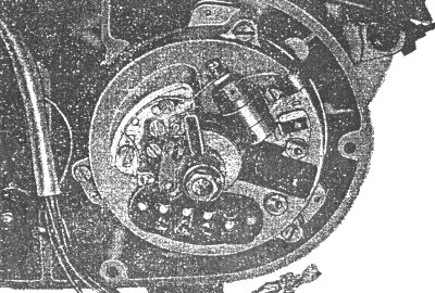
Fig. 137. Carbon brush holder demounted
Remove the carbon brush holder by loosening the two fastening screws.
Remove the stator with retaining cap after loosening the three fastening screws.
|
Fig. 138. Removing the retaining cap
Remove the rotor screw together with the cam. Separate the rotor from the
crankshaft by means of the pulling screw 02-MW 39-4.
|
Fig. 139. Pulling the rotor from the assembly
Take every care in demounting this component because the slip rings can be
damaged easily. The demounted parts must be protected from dirt, moisture and mechanical
damage.
6.1.8.2. Demounting the Rectifier
zum nächsten Punkt ; Index
NOTICE! Before demounting, disconnect the battery from the circuit of the
vehicle!
Remove the plug-in connections (U, V, W, 61, D+ and D-). For assembling at a later time, it
is advisable to mark the cables D+, D- and 61 distinctly because an exchange of these
connections will lead to the destruction of the diodes of the rectifier.
The connections U, V and W between three-phase current dynamo and rectifier may be exchanged
mutually without any damage occurring.
The rectifier is removed by loosening the fastening screws (6).
|
Fig. 140. Internal electrical equipment
- Regulator
- Capacitor 2.5 µF, 50 V
(omitted from August 1986)
- Ignition coil
- Line connector
- Rectifier
- Fastening screws
6.1.9. Dismantling the Three-phase Current Dynamo
6.1.9.1. Stator with Retaining Cap (Fig. 141)
zum nächsten Punkt ; Index
Carbon brush holder (9)
Loosen the plug-in connections of the carbon brushes. Remove the fastening screws. Withdraw
the holding clip (10).
At the same time, hold the carbon brushes (8) to prevent them from jumping out.
Check the carbon brushes and compression springs for wear.
Stator (6)
Unsolder the stator winding U/V/W.
Loosen the retaining angle (5).
With this, the stator as a complete component can be removed from the retaining cap
(7).
Rotor (4)
The rotor is not designed for being repaired.
A replacement of the slip ring body must be carried out in specialised regenerating
workshops.
6.1.9.2. Rectifier
zum nächsten Punkt ; Index
Loosen the four M 4 fastening screws and unsolder the rectifier stranded
wires from the plug-in tags U/V/W.
The three components can be tested and repaired separately (see Section
6.1.10.3.).
For pressing out defective positive or negative diodes, use a pressing-out mandrel.
For pressing new rectifiers in place, a special pressing-in mandrel must be used.
A maximum pressing force of 4,000 N (400 kp) is permissible. Take care that the mandrel
is applied exactly to the edge of the diode.
For handling and using semi-conductor diodes, the instructions given by the manufacturer
must be observed.
|
Fig. 141. Exploded view of the three-phase current dynamo
- Insulating plate with exciter diodes
- Diode plate (positive)
- Diode plate (negative)
- Rotor
- Retaining anale
- Stator
- Retaining cap
- Carbon brushes
- Carbon brush holder
- Holding clip
Fig. 142. Pressing-out mandrel
Round steel 22 TGL 11163 St 50 K TGL 0-1652
Fig. 143. Pressing-in mandrel
Round steel 22 TGL 11163 St 50 K TGL 0-1652
Fig. 144. Principle of diode testing
The measuring tips are applied to the anode and cathode connections of the
diodes.
When the positive measuring tip is applied to the anode and the test lamp lights up, then
the diode is serviceable.
When the lamp fails to light or when the test lamp lights up when the positive pole is
applied to the cathode, a diode fault is given and the diode must be replaced by a new
one.
In the diode plate positive (D+), the cathode are at the cooling plate, in case of the
negative diode plate (D-), the anodes are at the cooling plate.
The exciter diodes together with the cathode are at connection 61.
|
Fig. 145. Diode in perfect working order
Fig. 146. Check-test - diode in order
6.1.10.2. Checking the Stator
zum nächsten Punkt ; Index
Checking the stator winding for interturn short-circuit:
Between the individual phases (U/V/W, V/W), a resistance of about 0.32 ohm should be
measurable.
Checking the stator for magnetic shunt:
The stator is checked for magnetic shunt between the stator iron core and the winding
turns of the stator by interposing a test lamp and applying a test voltage of 24 V a.c.
All cables U/V/W must be separated from the stator. When the test lamp lights up, the
stator is defective and must be replaced.
6.1.10.3. Checking the Rotor
zum nächsten Punkt ; Index
Checking the rotor winding:
Measure the resistance by means of a resistance measuring bridge. It should be about
4.2 ± 0.3 ohm. After removing the component from the vehicle, the measurements
are taken at the slip rings.
The test tips should be applied only very slightly to the slip rings in order to prevent
damage to the graphite slip rings.
6.1.10.4. Checking the Length of the Carbon Brushes
zum nächsten Punkt ; Index
Demounting is to be performed according to Section
6.1.9.1.
When the length of the carbon brush falls below 9 mm, a new carbon brush must be
inserted.
6.1.11. Assembling Instructions
zum nächsten Punkt ; Index
Joints to be soldered have to be made by means of acid-free soldering
agents and protected from corrosion by electro-insulating protective lacquer (can be
soldered).
This protection should cover also newly soldered-in exciter diodes wholly. This can be
effected by dipping the whole rectifier. For this purpose, the plug-in connections must
be covered and after dipping remains of lacquer must be removed.
Stator
When mounting the stator into the retaining cap, take care that the groove of the stator
coincides with the groove in the retaining cap.
Permissible tightening torque for the stator fastening screw M 7-5.8
20 ± 2 Nm (2 ± 0.2 kpm)
Permissible tightening torque for the rotor fastening screw M 5-5.8
4 ± 0.5 Nm (0.4 ± 0.05 kpm)
It is advisable to fit the carbon brush holder after mounting the retaining
cap.
NOTICE!
Before connecting the battery, check the electric wiring. When the connections D+, D-, 61
and DF are exchanged by mistake, there is the danger of the destruction of the
semi-conductor elements and of additional units. Take care that the polarity of the
battery is observed (negative pole to earth) when connecting it.
Information about ignition timing and the application of the lubricating felt is given in
special documents for the vehicle.
6.1.12. Important Information
zum nächsten Punkt ; Index
For charging the battery by means of mains-operated charging sets, the
battery must be disconnected from the supply system of the vehicle.
When carrying out electric welding operations in the vehicle take care that the +-lines
of the supply system of the vehicle do not get into contact with the welding electrode.
The battery must be disconnected.
When the engine is running, connections between the three-phase current dynamo, the
rectifier and regulator must not be interrupted otherwise damage to the electrical
equipment may be the consequence.
For checking operations in the three-phase current dynamo and rectifier, the measuring
instruments must be provided with safe connections.
When operating the three-phase current dynamo without battery, a capacitor of 2.5 µF, 50 V,
must be connected between earth and terminal 51. (This is available in the ETZ as standard
equipment close by the line connector at the intake silencer.) ¹)
When the miniature fuse 2 A T (time-delay) between line DF and dynamo-regulator has failed,
in any case insert a fuse of the same type; never bridge the fuse in any other way! Without
this fuse, the motor-cycle can be operated without hesitation for short distances as long
as the battery voltage will suffice.
¹) Not applicable to rectifiers with diodes of an inverse voltage of 200 V from August
1986
6.2. Regulator
zum nächsten Punkt ; Index
The three-phase current dynamo is provided with a temperature-compensated,
positively regulating regulator with break characteristic. This single-system regulator of
14 V, 15 A, operates with voltage regulation. The current control limits the maximum
current to 15 A. A variable series resistor (connection side) and an adjustable resistor
are incorporated into the regulator.
6.2.1. Mounting
zum nächsten Punkt ; Index
In order to ensure proper functioning of the regulator, it is necessary to
fasten it so that it is not exposed to vibration.
This has been achieved fully in the ETZ because it is suspended elastically; the regulator
cut-out is provided with a pocket of foamed plastic and a rubber stopper for this
purpose.
When mounting every care must be taken that the regulator and cut-out are properly
inserted into the holder provided for this purpose.
6.2.2. Maintenance
zum nächsten Punkt ; Index
The maintenance of the regulator in general is restricted to the cleaning
of the connections. When the headlamp light is too faint, when there are difficulties in
starting, etc., do not look for the fault in the regulator neither intervene inexpertly but
first check the lines and their plug-in connections for proper condition and corrosion.
The regulator must not be touched by parts that may be put under the dual seat such as the
replacement inner tube, etc.
6.2.3. Adjustment
zum nächsten Punkt ; Index
Before the electrical adjustment, always a mechanical adjustment or a
correction of the mechanical adjustment must be made. This facilitates the electrical
adjustment and ensures that the required voltage/current characteristic is adhered
to.
An electrical adjustment of the regulator and cut-out IN THE VEHICLE is only a makeshift
and should be avoided in the interest of an optimum maintenance of the function of the
power supply system.
For adjusting the regulator and cut-out, they are placed on a test bench which is
continuously variable within a speed range from 0 to 7,000 rpm together with a dynamo
of the type in question.
In order to avoid errors in adjusting, the voltage must always be started from the
rotational speed "zero" of the dynamo. The voltage is measured between the
terminals D+ and D- of the regulator. The measuring instrument to be used should be at
least of quality class 1.5.
The following items have to be adjusted:
- Regulated voltage U3A
Voltage which is regulated over the full rotational speed range when the dynamo
is loaded with 3 A. The voltalte must remain within the specified tolerance range.
Short-time voltage peaks beyond the tolerance range at the beginning of the
lower-position or upper-position regulation should not, be mistaken for wrong
settings.
The regulated voltage may differe for about +0.2 to -0.1 V between end of the
lower-position regulation and beginning of the upper-position regulation (voltage
transient).
The voltage transient must not be adjusted too negatively otherwise the regulator
armature will "chatter", i.e. it will continuously oscillate between lower
position and upper position.
- Maximum load voltage UHL
Voltage which is regulated when the dynamo is loaded with 15 A at a rotational speed
of more than 3,800 rpm.
- Minimum operating current IAS
At this current, the current regulation is started.
Electrical adjustment values
The following values hold for a regulator temperature of (20 ± 5) °C.
| regulated voltage | | 13.8 to 14.6 V |
| maximum load voltage | | 13.0 to 13.5 V |
| minimum operating current | | 11.5 to 14.0 A |
|
Fig. 147. Mechanical adjustment of the regulator
- at least 0.3 mm
- 0.8 to 1.1 mm
- 0.5 ± 0.1 mm
- 0.5 ± 0.1 mm
- 1.4 to 1.5 mm
- Contacts of the voltage regulator
- Contact of the current regulator
(current limiting switch)
NOTICE!
A change of the regulated voltage and of the minimum operating current is to be carried
out only by carefully bending the spring holder. Do not bend the contact tags!
6.2.4. Damages and Their Causes
zum nächsten Punkt ; Index
This subject has already been dealt with in Section 6.1.
where the most important things have already been said.
In addition, observe the following:
An improper fitting of the protective cap of the regulator and cut-out leads to body
contact when the cap gets in contact with the core or with the contact angle of the
regulator and cut-out. Whenever opening the regulator, the fuses must be removed before
this operation. The lugs arranged at the side of the cap must be properly put into the
openings in the regulator base provided for this purpose. The wire bow must press firmly
on the cap.
6.3. Battery
zum nächsten Punkt ; Index
A flat lead battery with a nominal voltage of 12 V and a reated capacity
of 5.5 Ah is used.
For putting into operation, accumulator sulphuric acid (in the following text referred
to as electrolyte) of the density of 1.28 ± 0.01 g/cm³ (in the tropics 1.22
± 0.01 g/cm³, measured at (20 ± 2) °C, is filled into the battery.
All cells must be filled up to 5 mm on top of the separators or up to the given acid
level marking.
The temperature of the electrolyte must not exceed 25 °C when pouring it into the
battery.
After about 2 to 3 hours, plates and separators are fully soaked and the electrolyte level
has dropped.
|
Fig. 148. Battery arrangement
- Battery
- Flasher unit
- Fuse box
- Replacement electric bulbs
- Tool kit
- Battery holder
- Vent hose
Then, electrolyte of the same density and temperature has to be replenished
up to the top edge of the separators. Subsequently, the battery is charged with direct
current of 0.5 A.
During charging, the screw plugs of the battery must be opened.
Charging must be continued until all cells briskly and uniformly evolve gas and a voltage
of 2.5 to 2.7 per cell has been reached.
For 2 to 3 measurements taken at an interval of one hour, density of the electrolyte
(1.28 ± 0.01 g/cm³) and cell voltage must remain constant. During charging,
the temperature, of the electrolyte must not exceed 50 °C. At the end of charging, the
electrolyte level must again be checked.
Mounting the battery
Before the battery is mounted into the vehicle the two battery cables (red cable to the
positive pole, brown cable to the negative pole) must be connected to the battery and
preserved with some grease for battery terminals or acid-free vaseline. Subsequently the
battery can be mounted and the two battery cables connected to the fuse box.
IT SHOULD BE BORNE IN MIND:
red cable to red cable,
brown cable to brown cable!
The vent hose should be placed in such a way that acid which may escape
from it cannot get on varnished or metal parts.
Maintenance of the battery
The average service life of the battery is about 2 years. This period can be extended or
it may be shortened, depending on the care bestowed on the battery. The maintenance
operations are mainly restricted to the cleaning of the terminals - they must be preserved
with a thin film of grease for battery terminals - and the checking of the acid level.
When greasing the terminals take care that no grease can get into the cells.
When the acid level has dropped below the specified value, top up with distilled water
only.
When acid should have been spilled from the battery, then the density of the amount of acid
to be replenished must be selected in such a way that the density of the total amount of
acid in the battery in the charged state is 1.28 ± 0.01 g/cm³.
When the battery is not used, it must be re-charged with 0.5 A once every month.
6.4. Ignition
6.4.1. Ignition Coil
zum nächsten Punkt ; Index
The ignition coil is comparable with a transformer which transforms a low
voltalte into a high one. Since, as everybody knows, only an alternating voltage can be
transformed but the supply system of the motor-cycle is fed with a direct voltage, a
continuous voltage change must be caused, and this is done by the contact breaker together
with the capacitor.
|
Fig. 149. Ignition coil
The voltage of 12 V of the vehicle's supply system is transformed to the
ignition voltage of about 12,000 V. The two connecting bolts of the ignition coil are
marked.
Terminal 1 is connected with the contact breaker and terminal 15 with terminal 15/54 in
the ignition lock.
NOTICE!
When the engine is stationary, the ignition switched on and the contact breaker closed,
the ignition coil carries a current which heats the ignition coil after a certain time.
As a consequence, the insulating material will be destroyed. The ignition coil breaks
down and, hence, is useless.
6.4.2. Contact Breaker
zum nächsten Punkt ; Index
The design of the contact breaker is shown in Fig. 150.
On the one hand, the adjusting plate (4) is used as carrier of the plate (3) and the felt
wiper (11) and, on the other hand, for adjusting the firing point.
|
Fig. 150. Contact breaker
The bearing bolt (5) is fastened to the plate (3) with the fixed contact
(2 b); the lever (1) is pivoted an this bolt.
The contact (2 a) riveted to the right-hand end of the lever (1) is pressed against the
fixed contact (2 b) by the return spring (6) which also serves as conductor and one end
of the spring is propped on the connecting screw (7). The breaker points gap is precisely
adjusted by means of the eccentric screw (9) after loosening the fastening screw (8). The
felt wiper (11), which is slightly soaked in the special oil for contact breakers, should
be approached to the cam so far that it just touches the lobe of the cam.
When this neglected and the felt wiper is further advanced to the cam, the oil will be
pressed out of the felt and lubrication of the cam track is no longer ensured. Result:
the operating nose shows a high rate of wear - the breaker points gap and, thus, the
adjusted spark advance are changed.
The felt (10) serves for collecting the excessive supply of oil and must not be oiled
itself. When this felt is heavily contaminated, it must be replaced by a new one.
6.4.3. Spark Setting
zum nächsten Punkt ; Index
Adjusting the contact breaker points gap
Before starting adjusting, it is necessary to subject the breaker points to a check. For
this purpose the contacts should be removed (see Fig. 150).
The screw (7) is unscrewed, the current bar pressed up, the fastening screw (8) removed,
and the contact breaker base plate with contact breaker is taken off. When small burns
are visible on the contact areas, they can be removed by means of a fine emery file. In
case of heavy burn-up of the contacts, the contact breaker base plate with contact breaker
must be replaced.
When mounting take care that the adjusting plate (4) is clean and oil-free as well as the
complete contact breaker set. When this is neglected, intermittent firing and starting
difficulties will be the consequence. Remove the remains of old lubricants from the
bearing bolt, and fit the contact breaker hammer with some contact breaker oil. The
contact breaker contacts must be adjusted in such a manner that the contacts are parallel
to each other.
The crankshaft is turned for adjusting the breaker gap so far that the nose of the contact
breaker lever is arranged at the highest point of the cam.
The fastening screw (8) is loosened and, by means of the eccentric screw (9), the
contact gap is adjusted so that the feeler gauge can just be drawn through the gap.
Tighten the fastening screw (8) and once more check the contact gap by means of the
feeler gauge.
The set contact breaker gap must remain constant when the crankshaft is turned during the
full angle of opening, on no account should it become greater. Otherwise there will be a
cam eccentricity which will lead to intermittent firing at higher rotational speeds.
Setting the firing point
(2.5+0.5 mm before T.D.C. or 22°45' to 23°45' crank angle).
Setting is effected by means of the ignition setting gauge 29-50.801
and a test lamp.
|

Fig. 151. Ignition setting gauge 29-50.801 screwed in place
The ignition setting gauge is screwed into the thread for the
sparking-plug, and by turning the crankshaft clockwise, the scale of the setting gauge
is automatically adjusted to the top dead centre (T.D.C.).
|
Fig. 152. Test lamp clamped
The pointer of the setting gauge is on "0" of the trailing
scale when the piston is in T.D.C.
The test lamp with an electric bulb (G) of 12 V and maximum 2 W is clamped to the current
bar (from the contact breaker to the capacitor) at the positive side (1) and to the engine
casing for the cylinder at the negative side (2).
When turning the crankshaft through about 340° clockwise, the pointer of the setting
gauge will arrive above the scale values 5 to 4 (mm) at the firing point 2.5+0.5
(mm) of the trailing scale. When at this point the test lamp starts lighting (battery is
connected to the circuit of the vehicle and the ignition is switched on), then the firing
point is correctly set.
When the test lamp lights too early (e.g. between the scale values of 4 and 3), then the
contact breaker opens too early and the adjusting plate (4) must be displaced clockwise
after loosening the fastening screw (13). When the test lamp lights after the scale value
of 3 (e.g. at the scale value of 2), then the conctact breaker opens too late and the
adjusting plate (4) muest be displaced opposite to the sense of rotation, i.e.
anti-clockwise (see also Fig. 150).
After any adjustment of the adjusting plate (4), the contact breaker gap must be checked
and corrected, if necessary. The measurement of the firing point must be repeated until
the test lamp lights up at the scale value of 2.5+0.5 while the piston moves
upwards.
|
Fig. 153. Checking the firing point with the help of a current source outside the vehicle
dunkel dark
When for setting the firing point a current source out-side the vehicle
is used, then the test lamp will go out when the contact breaker opens.
NOTICE!
On no account should be contact breaker open earlier than 2.5+0.5 mm before
T.D.C. otherwise the combustion in the engine will be concluded too early and the
pressure of combustion presses on the piston already before T.D.C., a fact, which
means overheating, reduction of performance, and a high rate of wear of the engine.
6.4.4. Sparking-plug
zum nächsten Punkt ; Index
In essence, the sparking-plug consists of the three parts. These are
the insulating body, the central electrode and the steel casing with earth electrode.
The spark flashes over between central electrode and earth electrode, igniting the
fuel-air mixture.
The insulating body must have a very high breakdown strength. In order to ensure this
breakdown strength at any time, the sparking-plug should be treated carefully.
Due to inexpert treatment (blow, impact), almost invisible hair cracks may occur which
render the plug useless. The service life of a sparking-plug in two-stroke engines is
10,000 km of road operation on an average. After this performance, it is generally
correct TO REPLACE THE SPARKING PLUG BY A NEW ONE.
The ETZ is provided with a sparking-plug ZM 14/260. It is advisable to use always this
type of plug (observe the thermal value).
A lower thermal value in winter or a higher thermal value in summer will not offer any
advantage rather disadvantages; but in extreme climatic zones this may be necessary.
The correct seat of the plug should also be observed. The thread of the plug must be
flush with the thread in the cylinder cover. When the sparking-plug projects too far
into the combustion chamber (no packing ring or a ring that has been pressed flat is
under the plug) or when the plug is not properly screwed down (2 packing rings under
the plug), heat accumulation and overheating phenomena will be the result.
|
Fig. 154. Sparking-plug improperly screwed down or out
The maintenance requirements of the plug are relatively modest. The
electrode gap should be checked about every 2,500 km, and the plug electrodes must be
cleaned.
For changing plugs, a properly fitting sparking-plug wrench must be used in order to avoid
breakage of the insulating body (Fig. 154).
In any case, pay attention to the "plug appearance". After a longer use of the
plug, its appearance enables to draw conclusions as to the mode of operation of the engine,
the mixture formation, the fuel used, the carburetter tuning, and the suitability of the
plug for the engine.
The correct SPARKING-PLUG APPEARANCE:
The face of the sparking-plug thread is black and the insulating body tip with earth
electrode is grey-yellow to fawn.
6.4.5. Ignition Line Terminal (Plug Terminal)
zum nächsten Punkt ; Index
The ignition line terminal is designed to establish a connection between
sparking-plug and ignition cable and to screen the electrical field of the sparking-plug
externally.
In order to screen the sparking-plug properly, take care that the metallic armour
fastened to the ignition line terminal is correctly seated on the hexagon of the plug.
On no account should be metallic armour be removed otherwise interferences in VHF and
television reception will be caused.
Like the sparking-plug, the ignition line terminal must also be treated with every care.
Hair-line cracks in the insulating body which lead to tracking render is useless. When
the plug terminal is moist, dirty or oiled up in its interior, irregular firing will be
the consequence.
6.4.6. Faults in the Ignition System
zum nächsten Punkt ; Index
Due to wear and aging of the individual devices, faults may be caused in
the ignition system.
Below some of the frequently occurring causes and their effects are mentioned:
- Cam travel badly lubricated
wear of the nose of the contact breaker contact gap too small or no gap at all =
starting difficulties,
irregular running of the engine,
reduction of performance
- Breakdown of capacitor
high wear an contact =
irregular firing at higher rotational speeds
- Setting the contact gap in case of severe pitting
on the contact surfaces
the true distance is too great =
irregular firing at higher rotational speeds,
weak ignition spark,
reduction of output
- Crankshaft bearings badly worn
excessive eccentricity of the crankshaft and, hence, of the cam carbon brushes and
contact breaker "jump" =
- Insufficient pressing force of the contact spring (contact breaker)
contact breaker lever has no exact guide on the cam travel =
irregular firing at higher rotational speeds
IGNITION LINE TERMINAL:
- Dust and water is between the insulating body of the sparking-plug and the pressure part of the ignition line terminal =
starting difficulties,
irregular firing
- Due to improper treatment, the insulating body is cracked (hair cracks)
tracking towards earth =
starting difficulties,
weak ignition spark,
reduction in output
LINES:
- Defective insulation of the high-voltage line (ignition cable)
spark flashing to earth (cylinder cover) =
difficulties in starting especially in moist weather,
irrigular firing at high rotational speeds
- Broken lines
short circuit =
- Flat plug-in connections heavily corroded
very high contact resistance =
the voltage applied to the various devices is too low
6.5. Lighting and Signalling Installation
6.5.1. Headlamp
zum nächsten Punkt ; Index
The headlamp is opened, by loosening the fillister-head screw and
removing the front part of the headlamp housing. The front parts consists of the
chromium-plated front ring, the reflector with diffusing screen, the twin-filament
bulb and the town-light lamp and their holders.
|
Fig. 155. Headlamp housing
Fig. 156. Line connector for headlamp and internal electric devices (open)
In the headlamp housing, there are two line connectors (1) and
one earth point screw (2) which is used as a collector of all earth cables passed
into the headlamp.
NOTICE! As a line connector, only that one which is shown in Fig. 156
should be used!
When replacing the twin-filament bulb, pay attention to the following:
The clamping piece (part of thermosetting plastic) which establishes the electric
connection to the lamp must be withdrawn straight - do not tilt it - otherwise
the contact plates will be distorted. As a consequence, the current supply may be
interrupted.
The cables which lead to the terminals 31, 56 a, 56 b need not be disconnected.
It is advisable, however, to check them for tight fit. Only cable 58 (town light)
must be disconnected.
The holder (1) for the twin-filament bulb and the townlight lamp is loosened by
raising the retaining spring (H) from the upper plate nose of the reflector. Then,
the twin-filament bulb can be taken out the reflector. The glass bulb of the lamp
must not be touched with the bare hand. Even clean fingers leave grease traces!
When mounting, take care that the nose at the lamp cap is properly fitted into the
cut-out of the reflector.
|
Fig. 157. Front part of the headlamp with lamp holder
In case of insufficient illumination of the carriageway the contact
points of the lead to the twin-filament bulb must be checked and, if required,
carefully cleaned.
DIRTY CONTACTS CAUSE A CONSIDERABLE VOLTAGE DROP!
In older vehicles, the reflector may haue become doll. In the interest of your own
safety it is necessary to replace it by a new one. The diffusing screen and the
reflector are glued together, they cannot be replaced individually.
A very important work is the adjustment of the headlamp. It serves for the safety of
the other road users and for your safety.
After loosening the fastening nut (1), the headlamp can be adjusted.
|
Fig. 158. Adjusting the headlamp
The correct adjustment of tue headlamp passing beam is carried out
according to the scheme given in Fig. 159.
|
Fig. 159. Headlamp adjustment scheme
| Scheinwerfer-Mitte | centre of the headlamp |
| Schirm | screen |
The vehicle is placed according to the scheme and loaded so that the
main operating conditions are represented. Consequently, the spring-loaded suspension
units are set to "hard" or "soft".
The bright-dark boundary must exactly coincide with the Z-line and the angle must be
between the lines V-V and W-W. When the headlamp has been adjusted according to these
instructions, then the bright-dark boundary will have the correct height in all
operating and load conditions.
6.5.2. Combined Stop, Tail, Number-plate Lighting Fitting
zum nächsten Punkt ; Index
The stop, tail and number-plate lighting fitting is provided with ball
lamps which are kept in holders with bayonet catch, as is generally accepted.
|
Fig. 160. Combined stop, tail, number-plate lighting fitting, interior (partly sectional view)
The electric bulbs and cable connections are accessible after
turning out the fastening screws (arrows) and removing the light emitting pane.
Firm, non-corroded connections are also of importance to the combined stop, tail and
number-plate lighting fitting. When mounting, after placing the packing, screw the
light emitting pane in such a way that the combined lighting fitting is protected
from moisture but that the light emitting pane does not break.
6.5.3. Ignition-light Switch
zum nächsten Punkt ; Index
The ignition-light switch is the main switch of the electrical
system of the vehicle.
It is used for switching (see Fig. 161 and wiring diagram. Fig.
170)
- All loads switched off,
ignition key can be withdrawn
- Parking position at night (town light)
ignition key can be withdrawn
- Operation during day-time (ignition switched on, giving a push with the 2nd speed
engaged; this is possible when the battery is discharged or without battery)
ignition key cannot be withdrawn
- Ignition switched on, town light lights,
ignition key cannot be withdrawn
- Riding at night, ignition and main light switched on
ignition key cannot be
withdrawn
|
Fig. 161. Switch positions of the ignition-light switch
Fig. 162. Exploded view of the instrument holders
- Deluxe model
- Standard design
Demounting and mounting the ignition-light switch is shown in Fig.
162. In the deluxe model (A in Fig. 162), the
instrument (handle-bar) holder (1) must be unscrewed from the upper clamping head.
Then, the protective cap (2) and the ignition-light switch (3) are accessible.
In order to be in a position to put the cables on the correct tags after a replacement
of the ignition-light switch, the individual connections are once more clearly
represented in Fig. 163.
|
Fig. 163. Connections of the ignition-light switch
The ignition-light switch shown in Fig. 163 cannot be used for older MZ
types because the former switch position (5) is no longer switched electrically. On the
other hand, an ignition-light switch of the older types can also be used for the ETZ.
MOUNTING INSTRUCTION:
The arrow in Fig. 163 shows the mounting position of the ignition-light
switch in travel direction, connections downward.
6.5.4. Switch Combination at the Handle-Bars
zum nächsten Punkt ; Index
The switch combination at the left-hand handle-bar contains the following
switches (Fig. 164):
- Dimmer switch
- Switch for direction indicator
(L) flashing-light left-hand side
(R) flashing-light right-hand side
- Switch for horn
- Switch for by-pass light signal
|
Fig. 164. Switch combination at the handle-bars
The individual switches are fastened in the casing by means of sheet
metal screws (switch for direction indicator A and switch for horn B1 and
switch for by-pass light signal B2) or by actuating slide and spring (dimmer
switch C). The cables are soldered to the switches already by the manufacturer.
When fastening the combination switch to the handle-bars, install the thin cable strand
over the handle-bars, the thick cable strand under the handle-bars. The
two cable strands must be passed out of the switch downwards. They must not be
squeezed.
|
Fig. 165. Mounting the switch combination at the handle-bars
Fig. 166. Individual switches of the switch combination at the handle-bars
NOTICE!
The switch combination of the "Simson S 51" light motor-cycles cannot be
used for the ETZ because different cables are soldered to the switches otherwise equal
to those of MZ!
6.5.5. Stop-light Switch
zum nächsten Punkt ; Index
In the design with disk brake, two stop-light switches are installed.
The front drum brake can also be provided with a stop-light switch which at the hand-brake
lever corresponds to the switch of the disk-brake design.
For adjusting the stop-light switch, the plug-and-socket connection (2) is loosened and
the check nut slackened back until the rear nut can be properly handled by means of an
open-ended spanner. This nut is slackened back through a quarter of a revolution.
Then an assistant presses the brake pedal down until the brake shoes start sliding on
the brake drum when the rear wheel is turned. The brake lever must be retained in this
position and the adjusting screw turned until the stop light flashes up.
|
Fig. 167. Adjusting the rear wheel brake and the stop-light switch
- Adjusting nut of the brake
For this work, the ignition must be switched on and the cable is to
be connected. Subsequently, the two nuts must be tightened. The rear nut must be
tightened very carefully because the insulating bush is a part of plastic. In this
connection, the adjusting screw (3) must be secured against turning by means of a
screw-driver.
When the adjusting range is insufficient, then the back rest must be removed and the
contact spring at the cam spindle must be re-adjusted.
6.5.6. Flashing-light Direction Indicator System
zum nächsten Punkt ; Index
The ETZ has a 4-indicator flashing-light direction indication system
provided with 21-watt ball lamps.
When the adjusting range is insufficient, then the back to be re-inserted. Other lamps,
e.g. 15 watt, change the specified flashing frequency of 90 ± 30
periods/minute.
Direction indication is checked by a control lighting fitting (4 in Fig.
171).
|
Fig. 168. Flashing indicator, front
- Rim for checking the flashing function
- Plastic reflector
- Terminals
- Packing
The two front flashing indicator diffusing screens are provided with
a larger rim (1) than the two rear indicators. This rim is also intended to check the
flashing-light direction indicator system.
The failure of one flashing indicator is indicated by an increased flashing frequency
( >150 periods/minute) of the other flashing indicators.
The entire system is secured means of a 4-A fuse.
The flasher unit is elastically suspended with the connections downward at the battery
holding cover.
NOTICE!
The line with positive potential arriving from the ignition lock is to be connected
to terminal 49 of the flasher unit and the line arriving from the flasher switch with
negative potential to terminal 49 a of the flasher unit.
|
Fig. 169. Flashing indicator, rear
- Packing
6.5.7. Horn
zum nächsten Punkt ; Index
The horn is fastened to the frame under the fuel tank.
Before the cylinder cover or the cylinder can be demounted, the horn must be
unscrewed.
When, upon actuation of the pressure switch, the horn fails to produce the required
sound level, then the feeder cables, their connections and the pressure switch must
be checked for dirty points of contact. In this case, the applied voltage will be too
low.
If this not the cause, then slightly turn the adjusting screw at the horn to the left
or right by way of trial, until the sound will again be loud enough.
6.5.8. Wiring Diagram and Circuit Diagram
zum nächsten Punkt ; Index
For repairs in the various loads and the other electrical installation,
the wiring diagram (Fig. 170) furnishes the required data on cable
run and cable colours.
The circuit diagram is included in this Repair Manual in the form
of a folder.
NOTICE!
On the enclosed, coloured circuit diagram, in the 12-V system, the cable represented
black from the external
|
Fig. 170. Wiring diagram
Legend for Fig. 170, wiring diagram
| 1 | Battery |
| 1a | Capacitor |
| 2 | Ignition-light switch |
| 3 | Dynamo |
| 4 | Rectifier |
| 5 | Regulator |
| 6 | Charging control lighting fitting (in the standard design also for checking the direction indicators) |
| 7 | Idle gear control lamp (only in deluxe model) |
| 7a | Switch for idle gear control lamp |
| 8 | Switch for Korn (switch combination at the handle-bars) |
| 9 | Horn |
| 10 | Switch for by-pass light signal (switch combination at the handle-bars) |
| 11 | Dimmer switch (switch combination at the handle-bars) |
| 12 | Control lamp for high headlight beam |
| 13 | Lamp for headlamp |
| a | high beam |
| b | passing beam |
| 14 | Illumination for revolution counter scale (only in deluxe model) |
| 15 | Illumination for speedometer scale |
| 16 | Town light (parking light, in headlamp) |
| 17 | Tail light and number-plate illumination (in the combined stop, tail and number-plate lighting fitting, bottom) |
| 17a | not applicable to ETZ 125/150 |
| 17b | not applicable to ETZ 125/150 |
| 18 | Ignition coil |
| 19 | Contact breaker of the ignition System |
| 20 | Sparking plug with screened terminal |
| 21 | Stop-light switch - front wheel brake |
| 22 | Stop-light switch - rear wheel brake |
| 23 | Stop light (in the tail lighting fitting, top) |
| 24 | Flasher unit |
| 25 | Switch for direction indication (switch combination at the handle-bars) |
| 26 | Control lamp for direction indication (only deluxe mode) |
| 27 | Flashing-light direction indicator, front left |
| 28 | Flashing-light direction indicator, rear left |
| 29 | Flashing-light direction indicator, front right |
| 30 | Flashing-light direction indicator, rear right |
| 30a | not applicable to ETZ 125/150 |
| 31 | Circuit symbols for: |
| a | Flat plug |
| b | Sleeve for flat plug-in connection or socket |
| c | Earth |
| d | Detachable connection (screw, terminal) |
| e | Fixed connection |
| LVR | Line connector in headlamp, right-hand side |
| o | top |
| u | bottom |
| v | front |
| x | occupied connection |
| LVL | Line connector in headlamp, left-band side |
| o | top |
| u | bottom |
| v | front |
| x | occupied connection, |
| LVF | Line connector at cycle parts, on top of the filter housing |
| v | front |
| h | rear |
| x | occupied connection |
| Si | Fuse box |
| l | left |
| r | right |
| MA | Earth point of headlamp |
| MB | Earth point of stop, tail, number-plate lighting fltting |
| ML | Earth of lamp for headlamp |
| MC | Earth point of vehicle (at line connector at cycle parts) |
| MD | Earth point of dynarno |
| MT | Earth point of speedometer |
| Cable colours |
| German abbreviation | Meaning | | German abbreviation | Meaning |
| br | brown | | sw/rt | black-red |
| rt/sw | red-black | | sw/bl | black-blue |
| sw | black | | sw/gn | black-green |
| sw/ws | black-white | | ws | white |
| ws/sw | white-black | | gn | green |
| gr | grey | | gn/bl | green-blue |
| gn/rt | green-red | | bl/ws | blue-White |
| bl | blue | | rt/ge | red-yellow |
| ge | yellow | | br/sw | brown-black |
| rt | red | | | |
¹) Dash-dotted conductors are only present in the standard design
²) Dashed conductors are only present in the deluxe model
right-hand connection of the line connector to the stop light in
the motor-cycle is installed in brown/black and the cable represented
red between regulator and rectifier is installed in red/yellow
colour (see also wiring diagram, Fig. 170).
6.6. Instruments and Indicator Lamps
zum nächsten Punkt ; Index
The arrangement of the instruments is shown in Fig. 162.
The standard design of the ETZ is provided only with a speedometer (at the right-hand
side in the instrument holder).
The deluxe model possesses in addition to the speedometer, also arranged at the right-hand
side, a mechanically driven revolution counter arranged at the left-hand side (see Fig.
171).
The arrangement and meaning of the indicator lamps is shown in Fig. 171.
About wiring and connection with other electrical devices, the necessary information
is given in the wiring diagram (Fig. 170).
Speedometer and revolution counter are illuminated when riding at night. For this
purpose, the lamps designated by (3) in Fig. 172 are used which
receive earth via the flat plug-in connection (4). The function of the lamps identified
by (1) is shown in Fig. 171. The
|
Fig. 171. Arrangement of the indicator lamps
- Idle gear indication, yellow (only deluxe model)
- Control lamp for dynamo, red (only deluxe model)
- High-beam head-light indicator, blue
- Control of the direction indicators, green
(in the standard design it is also the control lamp for the dynamo)
missing electrical potential is fed to the control lamps (1) via the
flat plug-in connections (2).
The removal of the lamps from the instruments is possible when the flat plugs have
been withdrawn from the vertical connections of the lamps. Then, the lamps can easily
be drawn out of the instrument housing.
|
Fig. 172. Arrangement of the lamps in the instruments
7. Induction System
7.1. Description and Function of the System
zum nächsten Punkt ; Index
The entire induction equipment is an integrated system which is mated
with the engine to an optimum degree. Any change in this system will impair output,
fuel consumption, rate of wear, etc.
The induction system starts with the hole arranged under the regulator and ends with
the inlet port of the cylinder. There should be not point in the whole system where
air can be drawn in additionally to the holes provided for this purpose.
The air and the fuel-air mixture from the carburetter must pass through the following
path in order to get into the crankcase:
Air is sucked up through opening (A) of the intake pipe (1), see Fig. 174.
The intake pipe serves for silencing and air stilling.
After leaving the intake pipe, the air flows back into the frame carrier and enters
the air filter housing tightly screwed to the frame tube (L in Fig.
173).
|
Fig. 173. Intake silencer and air filter
When passing through the air filter, the air is cleaned. The dust
particles contained in the air adhere to the filter. The pressure differences
caused by intake vibrations are neutralised to a high degree in the intake silencer
compartment (1).
Then the air is drawn through the connecting piece (2), which is fastened to the
carburetter by the clamping ring (3), to the carburetter.
In the carburetter, the incoming air is mixed with the atomised fuel in a certain
ratio. This fuel-air mixture then passes through the intake port into the crankcase
of the engine casing.
7.1.1. Air Filter
zum nächsten Punkt ; Index
For the ETZ, a dry air filter is used. The air filter (4) is arranged
in the air filter housing.
It is centred at once face in the engine casing and at the other face by a cup (5)
which is guided by and fastened on a threaded bolt (Fig. 173).
In order that the filter is properly sealed at its two faces, the cup (5) and the
cover (7) must be screwed together in such a way that the air filter is firmly
seated and the packing (6) can fulfil its function.
The air filter is accesible after removing the battery. The dust is deposited on
the external surface of the filter. This should be observed in cleaning. The dry
air filter should be carefully tapped for cleaning or brushed with a dry and clean
hair brush.
7.1.2. Intake Silencer
zum nächsten Punkt ; Index
The intake silencer consists of two light-alloy castings which are
screwed together so that they are non-detachable, thus forming the housing.
The air filter housing (L) is attached to this silencer housing.
The noise suppression compartment (1) serves for keeping the loudness level of the
intake noise at the permissible value and also as a reservoir for the air required
by the engine for combustion.
The intake silencer housing is connected to the frame by means of three screws.
The induction hose (1 in Fig. 174), which also serves for silencing,
is fastened to the rear end of the frame carrier directly in the opening in the
sheet-metal with the help of a groove in the rubber. A lug cast on the front end
of the hose (H) retains it in the opening (Ö) of the frame carrier.
|
Fig. 174. Mounting the intake pipe
The induction hose can be replaced when the induction system, the rear
wheel mudguard and the rear wheel have been removed.
A broom stick (S) or another wooden stick facilitates the induction of the lug (H) into
the opening (Ö).
7.1.3. Connecting Piece to Carburetter
zum nächsten Punkt ; Index
The connecting piece is a rubber moulding which establishes the
connection between intake silencer and carburetter. Care should be takem to see to it
that the wall of the hole in the intake silencer housing properly fits in the groove
in the connecting piece provided for this purpose, and that the other end of the
connecting piece is properly connected with the carburetter by means of a clamping
ring.
The connecting piece must be inspected, from time to time, for porous parts especially
within the portion of the folds.
7.1.4. Carburetter
zum nächsten Punkt ; Index
For the types ETZ 125/150, BVF carburetters of type 22 or 24 N 2 are
used. It is a carburetter with starting device.
7.1.4.1. Design and Function of the Carburetter
zum nächsten Punkt ; Index
The carburetter consists of two systems. To familiarise yourself
properly with their design and function, it is thought to be helpful to explain
each system separately.
1. Cold starting device
As the name of this system already implies, it is incorporated to facilitate the
starting of the engine from cold.
The starting device is shown in Fig. 175 (driving position, lever
for starting carburetter at the handlebars contacts the stop in forward direction)
and in Fig. 177 (cold) starting, lever for starting carburetter at
the handle-bars is drawn in the direction of the driver).
In the driving position of the lever for the starting carburetter at the handle-bars,
the packing (2) at the starter piston (1) must completely close the starter mixing
tube (3).
|
Fig. 175. Starter piston closed (driving position)
Fig. 176. Lever for starting carburetter
| 1. | Starting device closed |
| 2. | Starting device switched on |
| |
| Z. | Throttle twist-grip OFF |
| A. | Throttle twist-grip ON (full load) |
| B. | Friction brake throttle twist-grip, adjusting screw |
The cable control set screw (4) must be adjusted in such a way that
a clearance of about 1 mm is existing between cable control sheath and set screw.
When the lever for the starting carburetter at the handle-bars is moved into cold
start position (lever is drawn towards the driver), then the starten piston with
packing is raised and, consequently, the upper opening of the starter mixing tube
(A in Fig. 177) is released.
|
Fig. 177. Starter piston raised (cold start)
The fuel in the starter mixing tube is sucked up when starting
the engine and conducted through the starter duct (5 in Fig.
177) which ends in the intake duct after the throttle valve.
In order to have the underpressure required for cold starting in the starting
system, the throttle valve must be in the no-load position.
The starting device will be ineffective when, in starting the engine, the
throttle valve is moved beyond and above the no-load system!
The lower opening of the starter mixing tube ends in a separate compartment,
the starter duct, which is connected with the compartment for the central float
through the starter jet (6 in Fig. 177).
The hole of the starter jet is designed in such a way that, after sucking up
the amount of fuel given in the starter mixing tube, only such an amount of fuel
is allowed to be fed that the engine, with readily drawn starter lever, can just
cope with the fed too rich mixture.
The fuel required for starting is pre-mixed in the starter duct.
The air required is sucked up through a recess in the top edge of the partition
wall from the compartment for the central float. This compartment is ventilated
through a hole in the carburetter casing.
2. Carburetter
The fuel flows through the float needle valve (10 in Fig. 178)
into the float chamber. When the fuel level has reached a certain heigth, then
the float needle valve is closed by a sheet-metal nose (A in Fig.
183) which is arranged at the holder of the float.
When the engine is running, the partial load needle is drawn out of the needle
jet more or less (2) by accelerating and, consequently, the throttle valve is
raised for the same distance. The air sucked up by the engine passes through
the intake duct of the carburetter and past the atomising insert. Consequently,
the fuel is sucked up through the main jet and needle jet to the intake duct
which is at a higher level.
By the atomiser (11 in Fig. 178), the fuel is atomised and
mixed with the air flowing through. This ignitable fuel-air mixture is then fed
to the engine.
For an ignitable mixture for slow-running, the slow-running jet and the specified
adjustment of the slow-running air screw are responsible.
The needle position, i.e. the notch which the partial load needle is suspended,
is decisive for the correct ratio of mixing between fuel and air in the partial
load range.
Apart from fixing the partial load needle, the needle holder (13) has the task
of guiding the needle (upper plate of the needle holder).
For setting the needle, the lower plate (A) of the needle holder is decisive
(Fig. 179).
The needle holder (13) lies flat on the bottom of the throttle valve (14). The
latter, which is axially displaceable in its guide, is pressed into the initial
position (slow-running position) by a spring which is supported by the screw cap.
The spring force acts against the cable control force (see Fig.
178).
|
Fig. 178. Carburetter BVF 22 N 2 and 24 N 2 sectional view
- Starter duct
- Needle jet with main jet
- Slow-running jet
- Slow-running duct
- Idling bore
- Slow-running air screw
- Slow-running air hole
- Compensating air duct
- Valve stop screw
- Float needle valve
- Atomiser
- Partial load needle
- Needle holder
- Throttle valve
- Spring for throttle valve
- Cable control for throttle valve
| Kraftstoff | fuel |
| zum Motor | to engine |
| Luft | air |
Fig. 179. Partial load needle with needle holder
7.1.4.2. Fuel Level - Basic Setting
zum nächsten Punkt ; Index
For combustion in the engine, an ignitable fuel-air mixture in the
ratio of 1:15 is required (mean value).
When this ratio is changed, e.g. by feeding more air, (1:18), the mixture becomes
too lean.
When the proportion of air is lower, e. g. 1:13, the mixture is too rich and, thus,
not readily ignitable.
The fuel level to be kept constant in the float chamber is regulated by the float
needle valve and the float.
The setting of the fuel level is an essential contribution to the formation of this
fuel-air mixture.
When the fuel level is set too high this means the formation of a too rich mixture;
when it is too low, the mixture is lean.
This shows that the basic setting of the fuel level is of great importance.
The fuel level can be checked in the vehicle. Pre-conditions are a mechanically perfect
carburetter (faults such as a sticking float needle valve, defective float, etc. must
be removed before testing), a full fuel tank, a clean serviceable fuel shut-off rock,
and a test float chamber which you have to prepare yourself. For this purpose, a float
chamber that fits the carburetter must be provided with an opening of 20 mm x 20 mm
into which a Piacryl disk, about 2 mm in thickness, is glued with a fuelresistant
synthetic resin glue.
In the carburetters 22 N 2 and 24 N 2, the level of fuel in the float chamber, measured
from the sealing surface of the float chamber, is 12 ± 1 mm. Therefore,
markings at 11 mm and 13 mm must be provided an the Piacryl disk.
|
Fig. 180. Carburetter with test chamber
| 1. | Piacryl disk |
| H. | Measure of the height of the fuel level |
| Z. | Feed of fuel |
Before the fuel level is determined, the specified values for the
float adjustment must be checked with the carburetter removed from the vehicle.
First, the correct float must be mounted. In contrast to the other BVF carburetters,
the float of the carburetters 22/24 N 2 is provided with a boss (K) on the stop lever
(B) as distinctive mark.
Then, using a vernier caliper, the dimension e1 and e2 between sealing
surface of the carburetter casing and float have to be measured without packing;
where
e1 = 30 mm:
float needle valve closed, actuating tongue (A) is applied to the spring pin,
spring pin not pressed in (see also Figs. 182 and
183)
e2 = 32 mm:
float needle valve open, stop tongue (B) is applied to the carburetter casing
When the dimensions differ, then re-bend the hinged or the stop
tongue (B).
|
Fig. 181. Float setting - specified values
| A. | Actuating tongue for float needle valve |
| B. | Stop tongue |
| K. | Distinctive mark (boss) |
NOTICE!
The float bodies must be parallel and at the same level with respect
to each other.
The actuating tongue (A) must be parallel to the hinged lever.
|
Fig. 182. Sectional view of float needle valve
- Jet
- Float needle, closed position
- Valve body
- Spring pin, not pressed in
- Fuel feed
- Fuel outled

Fig. 183. Sectional view of carburetter lower part
- Float needle valve (closed, spring pin not pressed in)
- Float axle
- Needle Jet
- Main jet
- Float, left half, at position of dimension e1
- Slow-running jet
- Slow-running duct in throttle valve
- Partial load needle
- Throttle valve
- Measure of height of fuel level (12 ± 1 mm)
- Actuating tongue of float needle valve
- Stop tongue
For measuring and setting the fuel level, proceed as follows:
- Plug the test chamber with packing an the carburetter and retain it.
- Connect the fuel hose. In order to maintain the required fuel pressure, a fuel hose
of the necessary length must be used. Keep the carburetter at the motor-cycle in a
horizontal position and so deep that the fuel level in the fuel tank is actually
500 mm above the inlet socket at the carburetter.
- Open the fuel shut-off cock.
- When the fuel level is between the markings 11 mm and 13 mm, then the setting is
correct.
- When the fuel level is not correct, close the fuel shut-off cock, remove the test
chamber, pour the fuel into the fuel tank, and re-adjust the float.
| Fuel level | H < 11 mm: increase e1 |
| H > 13 mm: reduce e1 |
- Recept the checking operation until the fuel level is within the tolerance range.
NOTICE!
The fuel level in the float chamber must remain constant for at least 3 min,
otherwise there are still faults in the float needle valve or in the float.
- Fasten the original float - chamber and mount the carburetter.
7.1.4.3. Slow-running Adjustment
zum nächsten Punkt ; Index
In the interest of an optimum fuel consumption and the observance of
the limit for the emission of noxious substances specified by legal regulations, the
slow-running adjustment should be carried out with the help of measuring instruments
for the analysis of the CO emission.
Pre-conditions for an optimum slow-running adjustment are:
- an engine that is mechanically in perfect condition;
- good sealing of the induction system and the carburetter connections between engine
and induction system;
- proper air filter;
- correctly set advanced ignition and good condition of the ignition system;
- the engine must have operating temperature!
Since the probe of the measuring instrument must project at least 60
cm into the exhaust system, an adapter for attaching to the silencer is required. This
adapter (Fig. 184) can be fastened to the silencer by means of a
part of an air hose 2.75x18 having a width of about 100 mm.
At first an engine speed of 1,200 rpm must be regulated at the throttle stop screw of
the carburetter. By slowly turning the slow-running air screw, the CO portion in the
exhaust gas is set to 2.5 to 3.5 vol.%.
NOTICE!
The legally specified maximum value of 4.5 vol.% must not be exceed. Adjust the
slow-running air screw only within the specified limits (see "Technical
Data", Section 1.).
|
Fig. 184. Adapter for setting slow-running
x = 80.5 mm
Rohr pipe
After slow-running setting, adjust the slow-running speed by means of
the valve stop screw in such a way that the engine can be subjected to gear-shifting
without noise.
7.1.5. Intake Socket
zum nächsten Punkt ; Index
The intake socket is designed to fix the position of the carburetter
and to form the connecting link between carburetter and intake port of the cylinder.
It is fastened to the cylinder by means of hexagon-head screws.
To ensure that the heat of the cylinder is not transmitted to the carburetter, a
plastic flange (in the 7.5 kW (10 hp) FRG design with intake part 16 mm in dia.)
and two packings (on either side of the plastic flange) are placed between intake
socket and cylinder.
7.2. Fault Finding Procedure
7.2.1. Too Lean Mixture
zum nächsten Punkt ; Index
Identification symptoms for too lean a fuel-air mixture are:
- Heavy consumption of the electrodes of the sparking-plug.
- Welding beads appear at the sparking-plug.
- When riding in the range from half load to full load, the engine performance is
too low.
- The engine tends to stall.
Faults or damages which lead to the supply of too lean a mixture and
their remedies:
- Air filter not seated properly an the centring edge of the air filter casing.
- Remove the air filter and properly fit it into the centring edge.
- Air filter has been damaged due to negligence.
- Replace the air filter by a new one.
- Packings between air filter housing and intake silencer or between air filter housing
and frame defective.
- Replace the packings by new ones and properly tighten the screwed joints.
- Packing between dir filter housing and cover missing or defective.
- Fit or replace the packing.
- Connecting piece to carburetter defective or porous or not properly seated in the
hole of the intake silencer casing.
- Replace the conneting piece by a new one or align it.
- Intake socket porous.
Replace the intake socket by a new one or, if possible, seal it with artificial resin.
- Insulating flange cracked or porous; packings defective.
- The parts involved must be replaced by new ones.
- Insufficient fuel feed due to
- contamined fuel-shut-off cock,
- compressed rubber packing,
- hardened or defective fuel feed pipe,
- choked vent hole in tank cap.
- Remove the fuel shut-off cock and carefully clean each part of it separately.
- Replace the defective or hardened fuel feed pipe and the defective rubber packing
by new parts.
- Blow compressed air through the hole in the tank cap.
- Partial load needle is suspended too deep
- Supspend the partial load needle at a higher level, for one or several notches,
as required to obtain a normal mixing ratio.
- The float is deformed - the float needle valve is insufficiently opened.
- Set the correct fuel level in the float chamber.
- Float needle sticking.
- Polish the shaft of the float needle and the through bores of the valve body.
- Check the valve for foreign particles.
- Replace float needle and jet by new parts.
7.2.2. Too Rich Mixture
zum nächsten Punkt ; Index
Symptoms of faults associated with too rich a fuel-air mixture are
as follows:
- Engine fails to start readily.
- Engine output drops with increasing temperature of the engine.
- High fuel consumption.
- Inclination to "four-stroking".
- Sparking-plug of specified thermal value fouled.
- Emission of heavy smoke visible with the engine at operating temperature.
Faults or damages which lead to the supply of too rich a mixture
and their remedies:
- Dry air filter too old (more than 10,000 km of road operation).
- Replace the air filter by a new one.
- The dry air filter is wet.
Cause: air filter housing leaky - water has entered.
- Allow, the air filter to dry or, what is to be preferred, replace it.
- Partial load needle suspended at too high a level.
- Suspend the partial load needle at a lower level, one or several notches deeper,
until a normal mixing ratio is obtained.
- Wear of needle jet and partial load needle (more than 20,000 km of road operation).
- The two parts must be replaced by new ones.
- Float needle valve leaky.
Cause:
- Valve contaminated,
- Float needle worn.
- Clean the float valve;
- Mount a new float needle.
7.3. Oil dosing
zum nächsten Punkt ; Index
| Fuel | Octane number 88 without oil admixture |
| Engine lubrication | High-quality two-stroke engine oil. The oil is
kept in the oil reservoir (capacity about 1.3 l) under the intake muffler and is
pumped through a Mikuni oil pump into the crankcase. |
| Actuation of the pump | by means of the throttle twist-grip |
| Range of operation | with one oil filling up to 1,600 km, depending
on driving habit |
| Putting into operation | - fill the oil reservoir
- open the bleeder screw for about 3 to 4 revolutions and only close it again
when oil emerges free from air bubbles
- fill about 2 l of fuel-oil mixture
- ratio 50 : 1 - into the fuel tank and perform a trial ride of about 5 km
- switch on the pump
|
Care and maintenance
| Before any ride: | Check the oil level in the oil reservoir (oil level
inspection eye and marking on lower part of stopper). |
| After every 2,500 km: | Check the cable control for wear and the oil lines
for properly tight fit. |
| After every 5,000 km: | - Lubricate the actuating cable control.
- Check the adjustment of the pump and re-adjust it, if required (Fig.
185).
|
|
Fig. 185. Maintaining the dosing pump
- Bleeder screw
- Cable control adjusting screw
- Markings of the setting point
If the markings 3 are not opposite each other, then
- Remove the idling speed fuel supply by screwing out the stop screw of the throttle
valve;
- Set the engine speed to 1,200 rpm by means of the throttle twist-grip;
- operating adjusting screw 2, re-adjust the cable control until the markings coincide;
- Set the idling speed to 1,200 rpm.
| Repairs | - The oil pump is not designed for any repair.
If
necessary, have a new pump mounted. - The fastening screws have to be tightened
uniformly with a maximum torque of 2.5 Nm in order that the fastening flange of the
pump will not be distorted.
- Before putting into operation a new pump, bleed
it (1, Fig. 185) and adjust the pump newly.
|
Marking of the partial-load needles
From the beginning of the 4th quarter of 1984 the partial-load needles of all BVF
motor-cycle carburetters have been marked no longer with letters and figures but by,
turned-in grooves. This also applies to spare parts. At the same time, the partial-load
needles are provided with a new designation which is coded in the marking.
Example:
| | Partial-load needle | 2,5 | A | 5 | 1 | 2 |
| nominal size (shaft diameter in mm) | | x | | | | |
| shape of partial-load needle (position of the notches) | | | x | | | |
| number of notches (a) | | | | x | | |
| number of marking grooves (b) | | | | | x | |
| number of marking grooves (c) | | | | | | x |
- Float is distorted - float needle valve remains open in an excessive position.
- Set the correct fuel level in the float chamber.
- Main jet too large.
- Use another main jet with the same dimension marked on it (jets with the same
nominal dimension difier by their tolerances).
- Packing at starter piston defective.
- Replace the packing by a new one.
- Spring for starter piston has an insufficient pretension.
- Replace the spring by a new one.
- Sheath of the cable control for the starting device is without play; as a
consequence, the starter piston cannot properly seal the starter mixing tube.
- Adjust the cable control sheath so that a play of about 1 mm is ensured.
|
Fig. 186. New needle markings:
Marking
old | Marking
new |
| C3 | 2,5 A 511 |
| C6 | 2,5 A 512 |
| C8 | 2,5 A 513 |
Fig. 187. Set of special tools for ETZ 125/150
8.1. List of Special Tools
zum nächsten Punkt ; Index
Item
No. | | Reference
number | Drawing in
Repair Manual |
| 1 | Pulling device for bearing in control head | 22-51.006 | 1 |
| 2 | Centring bolt for swing arm (05-MW 26-4) | 89-99.055 | 2 |
| 3 | Expanding mandrel for wheel bearing (M 8-820-3) | 89-99.090 | 3 |
| 4 | Holding-up hammer for sprocket at gearbox | 31-50.404 | 4 |
| 5 | Assembling bridge | 22-50.430 | 5 |
| 6 | Pulling sleeve | 22-50.435 | 6 |
| 7 | Pressure spindle | 22-50.437 | 7 |
| 8 | Ball bearing extractor | 22-50.431 | 8 |
| 9 | Auxiliary ring for ball bearing extractor | | |
| | for bearing 6204 | 22-50.432 | 9 |
| | for bearing 6304 | 22-50.434 | 9 a |
| 10 | Holding-up hammer for clutch driver (01-MW 22-4) | 89-99.012 | 10 |
| 11 | Holding-up hammer for primary drive | 31-50.405 | 11 |
| 12 | Puller (12 MV 32-4) for sprocket wheel on crankshaft | 89-99.305 | 12 |
| 13 | Drift (11 MW 7-4) | 89-99.073 | 13 |
| 14 | Drift (12 MV 31-4) | 89-99.304 | 14 |
| 15 | Heating mandrel for bearing 02 and 03 | 31-50.406 | 15 |
| 16 | Heating mandrel for bearing 04 and 06 | 31-50.408 | 16 |
| 17 | Armature pulling screw (02-MW 39-4) | 89-99.026 | 17 |
| 18 | Ignition setting gauge | 29-50.801 | without |
| 19 | Gudgeon pin ejecting device | 22-50.010 | 18 |
| 20 | Piston support | 22-50.412 | 19 |
| 21 | Guide mandrel for gudgeon pin (02-MW 33-4) | 89-99.021 | 20 |
| 22 | Engine assembling device with auxiliary parts for EM 125/150 | 22-50.014 | without |
| - | Auxiliary tool for demounting and mounting the guide tubes | only intended for self-construction | 21 |
| - | Special wrench for shock absorber | | 22 |
| - | Assembly device for swing arm bearing | 22-50.455 | 23 |
| - | Demounting device for brake master cylinder | 30-51.043 | 24 |
8.2. Drawings for Special Tools
Index
1. Pulling device for bearing in control head 22-51.006
|
Teil 8 mit Festsitz eingepaßt Part 8 mounted with tight fit
| Einzelheit X | Detail X |
| Paßmaß | Dimension of fit |
| Abmaß | Deviation |
| Part | Quantity | Description | Material | Rough Size | Remarks |
| 1 | 1 | | C 45 | ø 30x80 | | hardened and tempered |
| 2 | 1 | tube 76x10 | St 35 hb | 75 long | welded part | |
| 3 | 1 | | St 38 b-2 | ø 65x10 | |
| 4 | 1 | | St 38 b-2 K | ø 8x130 | welded part | |
| 5 | 1 | hexagon-headscrew M 16x1.5x35 | | | TGL 0-961 |
| 6 | 1 | | St 38 b-2 K | ø 8x92 | | |
| 7 | 1 | | 16 Mn Cr 5 | ø 36x30 | | case hardened |
| 8 | 1 | circlip 28x1.6 | | | | TGL 0-9045 |
2. Centring bolt for swing arm (05-MW 26-4) 89-99.055
|
gehärtet und angelassen hardened and tempered
| Part | Quantity | Description | Material | Rough Size | Remarks |
| 1 | 1 | holder | St 60-2 k | 20x20x105 | |
| 2 | 1 | plug link D 0.8 B-1 | | | TGL 11796 |
| 3 | 1 | roller chain D 0.8 B-1, 19 links | | | TGL 11796 |
5. Assembling bridge 22-50.430
Weld seams : > 2.5 SG (CO2) II B TGL 14904/3-10 Mn S/5, ø 1.2 TGL 7253
|
| Part | Quantity | Description | Material | Rough Size | Remarks |
| 1 | 1 | basic body | U-steel 6 1/2 St 38 b-2 | 350 long | TGL 0-1026 |
| 2 | 1 | disk | St 38 b-2 k | ø 20x8 | TGL 0-1026 |
| 3 | 1 | plate | St 38 b-2 | 5x60x115 | TGL 0-1026 |
| 4 | 1 | bolt | St 38 b-2 | ø 12x55 | TGL 0-1026 |
| 5 | 1 | washer | R 5.8 | | TGL 0-440 |
6. Pulling sleeve 22-50.435
|
Zapfen gehärtet pin hardened
bearing 6204 22-50.432
all chamfers 1 x 45°
|
bearing 6304 22-50.434
all chamfers 1 x 45°
|
Gewinde weich thread soft
All non-dimensioned radii R = 1 mm
inserted, hardened - all non-dimensioned radii R = 1 mm
Kordel 1, 2 knurl 1, 2
beschriftet mit 03 marked with 03
beschriftet mit 02 marked with 02
beschriftet mit 04 marked with 04
beschriftet mit 06 marked with 06

Pressure member (3) must still be capable of being turned
scharfkantig ausgeführt made with Sharp edges
vernietet riveted
| Part | Quantity | Description | Material | Rough Size | Remarks |
| 1 | 1 | threaded piece | St 38 b-2 | 30x10x72 | TGL 7973 |
| 2 | 1 | spring-steel cross-bands | Ck 67 | 245x45 | TGL 7975 |
| 3 | 1 | pressure member | C 45 | ø 20x20 | TGL 7970 |
| 4 | 1 | lock | St 38 K | ø 8x100 | TGL 7970 |
| 5 | 1 | pin | St 38 K | ø 5x30 | TGL 7970 |
| 6 | 1 | hexagon-headscrew M 12x100 | | TGL 0-933 |
| 7 | 4 | washer ø 5.3 | | TGL 0-125 |
| 8 | 4 | fillister-head screw M 5x16 | | TGL 0-84 - 5 S |
19. Piston support 22-50.412
|


Rohr drücken tube to be pressed
Schweißnaht darf nicht überstehen weld seam must not project


| Part | Quantity | Description | Material | Rough Size | Remarks |
| 1 | 1 | clamping sleeve | C 60 | ø 40x107 | hardened and tempered |
| 2 | 1 | clamping ring | C 60 | ø 50x40 | hardened and tempered |
| 3 | 1 | washer 19 | | | TGL 0-125 |
| 4 | 1 | hexagon-headscrew M 18x1.5 | | | TGL 0-936 - 8.8 |
Index
|